TrustedTM AN-T80004 Application Note Field Loop Configuration TM The Trusted Input/Output (I/O) modules are designed to monitor field loops for alarm and field cable fault states. The configuration of field loops differs between modules. This application note: • explains the circuits required to allow line monitoring of field wiring.
TrustedTM AN-T80004 Field Loop Configuration Table of Contents Analogue Inputs ...................................................................................................................................... 5 Line monitoring ................................................................................................................................... 5 T8431 and T8432 Termination Options .............................................................................................
TrustedTM AN-T80004 Field Loop Configuration Short circuit in field wiring or load (state 5) .................................................................................. 29 Field fault (state 6) ....................................................................................................................... 29 Channel fault (state 7+)................................................................................................................ 29 No-load (Open Circuit) Threshold ...............
TrustedTM AN-T80004 Field Loop Configuration Floating Earth Systems and Loop Isolation ...................................................................................... 49 Hazardous Area Protection .............................................................................................................. 49 System installation ....................................................................................................................... 49 EEx certification ..................................
TrustedTM AN-T80004 Field Loop Configuration Analogue Inputs Line monitoring Field loops providing analogue input signals to a TrustedTM system do not require line monitoring components to be fitted to the field device, because the measured current acts as the proof of the presence of the line. However, analogue inputs should be checked for accuracy periodically because partial shorts will offset the measurement.
TrustedTM AN-T80004 Field Loop Configuration The T8842 Versatile Field Termination Assembly (VFTA) provides individually configurable channel circuits for a T8431 and other low voltage 40 channel modules. It also provides three-wire connection (24V supply, signal and zero volt reference). It requires a VFTA cable TC-211, 212, 511 or 512. Circuit configuration is given in PD-8842. Fuse ratings may be chosen up to a total of 3A per group of eight channels.
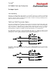
TrustedTM AN-T80004 Field Loop Configuration System circuit 24V Channel 0V This circuit cannot be used. Usually the current loop is not even returned to the system but is added to the field device’s own power zero volt reference. Therefore the only available measurement point for the current is the channel connection. The T8431 and T8432 are not designed to measure voltage with respect to the supply rail, and so the circuit above is not possible. The solution is to fit a current isolator device (e.g.
TrustedTM AN-T80004 Field Loop Configuration The current loop allows 4mA to drive the device electronics. However, most field devices need higher power. This must be provided with a separate power connection. This is now a three wire device. Note that the fuses on the FTA should not be replaced with higher rating fuses because a short between the fuse and the channel input may damage the channel. VFTAs include a zero volt terminal, but if FTAs are used, fit a separate zero volt terminal.
TrustedTM AN-T80004 Field Loop Configuration Millivolt inputs The T8840 allows a block of eight channels of a T8431 to be connected to thermocouple, RTD or other millivolt inputs using plug-in converters. It requires a VFTA cable TC-211, 212, 511 or 512, which provides separate plugs for each group of channels. This can be wired via a VFTA T8842 allowing some channels of the module to be used for current loops. Configuration options are given in PD-8840.
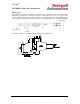
TrustedTM AN-T80004 Field Loop Configuration T8433 Termination Options The T8433 TrustedTM Isolated Analogue Input module has individually isolated inputs. These measure 0-22mA. The module has a three-wire connection for supply, reference and signal; the extra wires mean that there is only room for 20 channels. The module input circuit is completely isolated and requires an external supply of 4.5 to 8 volts, derived in the circuit below from the loop.
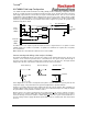
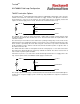
TrustedTM AN-T80004 Field Loop Configuration The T8834 FTA is a configurable version of the T8433. This also connects to I/O cables TC-601, 603, 701 or 703. It also contains a zener diode for the channel power and a precision resistor for the current TB3 - TB3 + TB2 + SUPPLY 7V5 REFERENCE TB1 A 100R 4K75 TB1 B SIGNAL TB2 to voltage conversion, but it may be wired in several different ways.
TrustedTM AN-T80004 Field Loop Configuration For field powered devices, sourcing current, where the channel current could go below 4mA (e.g. gas detector optics alarms): Isolated PSU + TB3 - TB3 + TB2 + SUPPLY 7V5 TB1 A 100R REFERENCE 4K75 TB1 B SIGNAL TB2 Since the current loop is on the negative side of the channel power, it is possible to configure the T8834 FTA to power and sense current-sinking devices, where the loop draws current away from the channel.
TrustedTM AN-T80004 Field Loop Configuration Configuration There are seven input voltage state thresholds detected by all of the analogue input modules, numbered 0 to 6. States 0 and 6 are ‘out of range’ indications, outside of the normal operating range. The remaining five are configurable using the System Configuration Manager. The voltage transition between each state can be split into a rising transition and a falling transition.
TrustedTM AN-T80004 Field Loop Configuration Threshold online update The channel thresholds can be read or written using the THRSHOUT and THRSHIN boards in the I/O connection table, through the Toolset Debugger’s online view. The thresholds are shown in raw units, at the same scaling as the AI board (0 = 4mA or 1V, 4096 = 20mA or 5V). To read a channel’s thresholds, enter the channel number on THRSHOUT channel 3, then change THRSHOUT channel 2 from 0 to 1. The thresholds will appear on the THRSHIN board.
TrustedTM AN-T80004 Field Loop Configuration Overvoltage Faults The analogue inputs are not designed to measure voltages up to 24V. The A/D conversion will reach its maximum at about 7 volts. Above this point, the measurement parameters will be at the maximum values. This causes module channel faults (0x52nn) to be reported, which appear as slice faults.
TrustedTM AN-T80004 Field Loop Configuration Digital Inputs Thresholds Digital inputs are essentially analogue inputs which are interpreted as digital. The voltage on the input circuit is measured and allocated to an input state using thresholds, similar to analogue inputs above. For digital inputs, the state bands are essential, since they define the digital input ‘off/open’ and ‘on/closed’ as well as line fault status.
TrustedTM AN-T80004 Field Loop Configuration Line Monitoring and Marshalling for Volt-Free Inputs Field loops providing digital input signals to a TrustedTM system need line monitoring components if they are safety related inputs or require assurance of operation. Defining the open and closed states nominally at 16 and 8 volts (as above) simplifies the selection of line monitoring components. There are two types of 24V dc digital input module; T8402 (dual) and T8403 (TMR).
TrustedTM AN-T80004 Field Loop Configuration T8403 TMR Inputs When using the TrustedTM TMR 24V dc Digital Input Module T8403 with volt-free contact field devices, it is better to clamp the voltages rather than rely on potential dividers, because the loop termination resistor is inside the module and will be paralleled with another during swapping, changing the resistance. The field loop configuration shown in the diagram below is recommended for T8403 (and is also acceptable for T8402).
TrustedTM AN-T80004 Field Loop Configuration For systems conforming to AANSI/ISA non-incendive hazardous area specifications, the T8801 replaces the fuses with resistors to limit the available power. In this case, the field zener diodes will only dissipate 100mW on a full short circuit to zero volts. T8423 35-120V dc Digital Inputs The T8423 is similar to the T8403, but is rated for any supply voltage from the upper range of the T8403 up to 140 volts dc maximum.
TrustedTM AN-T80004 Field Loop Configuration T8424 120V ac Digital Input The T8424 is actually a T8431 analogue input module with different firmware (and labels). It has to be used with a T8824 FTA and TC-211, 212, 511 or 512 I/O cables. The T8824 FTA contains resistor networks that divide the voltage down to analogue input levels. If any resistor goes open circuit, the overall change in value will not change the input state.
TrustedTM AN-T80004 Field Loop Configuration Non volt-free digital inputs The information above is for isolated volt-free contacts, which are the simplest kind of digital input. The system is able to apply its own voltage and measure the effect without any external influences apart from the switch state. However, the input device or system must isolate the contact, e.g. using a relay or solid state switch.
TrustedTM AN-T80004 Field Loop Configuration Field powered inputs These inputs appear as a voltage signal, powered by the remote device. This is likely to be another PLC, which may or may not have isolated outputs. There is an inherent danger with field powered inputs: the system supplies may be on different mains phases, causing damaging potential differences, unsafe wiring, or even just massive signal noise on semi-isolated channels. All field powered inputs must therefore be isolated.
TrustedTM AN-T80004 Field Loop Configuration Hall Effect and Open Collector/Open Drain These devices are all essentially semiconductor switches in diferent configurations. A Hall Effect sensor is a simple proximity detector, using a semiconductor. When magnetic material is nearby, the semiconductor will conduct like a diode (one way). When the device is away from magnetic material, it stops conducting. It may be imagined as a transistor without a base connection.
TrustedTM AN-T80004 Field Loop Configuration Zone Interface and Valve Monitor Inputs The T8448 and T8449 modules have the same hardware as the T8451 digital output module, but with different firmware fitted to change their operation. The T8448 Zone Interface Module may have its channels individually configured as inputs or outputs and is intended to provide all the I/O needed for a single fire zone.
TrustedTM AN-T80004 Field Loop Configuration Configuration T8448 and T8449 inputs may be monitored by the application through either the STATE or the AI boards on the equipment definition. There is no Boolean point available for digital inputs. The AI board provides the measured voltage in 500ths of a volt (0V = 0, 24V = 12,000 etc.) This can be changed to engineering units with a conversion table, as for analogue inputs.
TrustedTM AN-T80004 Field Loop Configuration Frequency/Pulse Inputs The T8442 Speed Monitor Module is designed to monitor the speed of a rotating machine (turbine etc.) and provide over-speed and over-acceleration trip outputs to a very high integrity. Its normal purpose is described in its Product Description PD-T8442. This document covers possible alternative uses. It is therefore ideal for measuring frequency inputs up to 30,000Hz with an accuracy of 1Hz or 0.01%, whichever is greater.
TrustedTM AN-T80004 Field Loop Configuration Digital Outputs Power Groups Digital Output module channels are arranged in groups of eight. Forty channel modules therefore have five groups, thirty two channel modules have four and sixteen channel modules have two. 1 Group 1 8 9 Group 2 16 17 Group 3 24 25 Group 4 32 33 Group 5 40 Each group is isolated from each other, allowing different supply voltages to be used for each group.
TrustedTM AN-T80004 Field Loop Configuration Line Monitoring Outputs do not have threshold templates. Instead, the state of an output is determined automatically by measurement of its voltage and current with few user-definable settings. The state is the module’s measurement of the output condition and is not the same as the output command. Each of the three slices of an output module makes a judgement on the state of the output. The majority vote is reported to the application through the STATE board.
TrustedTM AN-T80004 Field Loop Configuration Output energised/on (state 4) This occurs when the channel output current is above the no-load threshold and below the short circuit limit, an adequate field supply voltage is present and the voltage is above the Off threshold. This proves that the output is energising the load and the load is within the module’s specification. Short circuit in field wiring or load (state 5) This is detected by separate logic that monitors the output current.
TrustedTM AN-T80004 Field Loop Configuration No-load (Open Circuit) Threshold Triplicated Modules 8448, 8449, 8451, 8461, 8471 (See later for 8472, 8473) The No-Load threshold settings are a common cause of confusion, leading to copying of settings from other configurations without understanding. For this reason they are covered in more detail here. The no-load threshold is a current in milliamps per channel slice below which the channel is declared open circuit.
TrustedTM AN-T80004 Field Loop Configuration It is advised to add load resistors to loads under about 20 to 25mA to increase them above the minimum threshold. It is also possible to apply a threshold of 3mA to a group, but only if the group has entirely light loads; this setting will otherwise clearly increase the chances of noise causing a false positive diagnosis, causing a potential shutdown. Quad Structure Modules 8472, 8473 These modules do not have the triplicated output circuit described above.
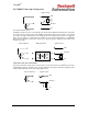
TrustedTM AN-T80004 Field Loop Configuration Termination Powered digital output terminations are very simple, with minor additions to suit each module type. Field Supply Output module for reference only Load The above diagram is complete for T8448 and T8449 outputs, T8451 and T8461. T8471 requires 330K resistors (0.25W) in parallel with the load and also on unused channels, to provide termination to the diagnostic tests, so they can distinguish between an open circuit and a stuck-on fault.
TrustedTM AN-T80004 Field Loop Configuration T8850 and T8870 FTAs The T8850 and T8870 FTAs are also a simple straight-through connection, but also include power supply indicating LEDs. However, these are only relevant if using integral power cables, where the field power is wired to the FTA and connects through the I/O cable to the module. The T8850 is designed for 24V dc operation but would be appropriate for 48V dc operation if the power supply indicating LEDs are not connected.
TrustedTM AN-T80004 Field Loop Configuration ‘Standard’ cables have two short tails on the chassis end. These cables are TC-205, 207, 505 or 507. One tail connects to the field power supply via a T8290 or T8297 distribution unit. The other connects to the power supply zero volts to provide a reference to the module for measuring the supply voltage, through a plug which fits onto a T8290.
TrustedTM AN-T80004 Field Loop Configuration Terminating Resistors Unused outputs should be commanded off/de-energised. These need a resistor to satisfy the diagnostic logic, which is wired from the channel output to zero volts. This also prevents the need to force channels to a healthy state. Field Supply Output module for reference only Load The following values will drain sufficient leakage current to move the channel voltage down to the state 2 (off) range. T8448, T8449, T8451 4K7 0.5W T8461 10K 0.
TrustedTM AN-T80004 Field Loop Configuration If the relay load current is less than the minimum, an extra load resistor is required as described in the previous section. Hazardous area outputs Digital outputs are not intrinsically safe or non-incendive. Separate power-limiting devices should be fitted to satisfy the regulations in force. For EEx ‘d’ devices, mounted in sealed explosion-proof housings, direct connection is allowed because the device housing provides the protection.
TrustedTM AN-T80004 Field Loop Configuration Caution Devices that cannot be reliably line monitored when de-energised must not be used for safety related energise-to-action applications. State 6 may also be caused by external lamp tests, or otherwise when the outputs are powered from an external source. It is recommended to configure lamp tests through the system application so that there are no secondary connections powering the load.
TrustedTM AN-T80004 Field Loop Configuration Analogue Outputs The Trusted T8480 Analogue Output module may be considered as a current controlled digital output module and it has similar termination and characteristics. The specific differences are listed in this section. Module circuit Like digital output modules, the T8480 has channels arranged in power groups, each supplied by a common failsafe switch.
TrustedTM AN-T80004 Field Loop Configuration Output energised (state 4) This state occurs with a load fitted when the current demand is zero or positive and is thus the expected state of a healthy output. Current demand cannot be met (state 6) (There is no short circuit state 5 for analogue current outputs; the channel will drive a short circuit with the required current). This occurs when the required current exceeds the capabilities of the channel.
TrustedTM AN-T80004 Field Loop Configuration Pulse Outputs Applications have occasionally required pulse-width modulated outputs. These may be used to control valve positioners using open and close pulses. Other applications may require accurate control of output pulse times. The T8449 Valve Monitor module is normally used to add valve testing to an output drive. The output is briefly switched to the opposite state and the feedback input channel is monitored by the module to check that the valve has moved.
TrustedTM AN-T80004 Field Loop Configuration IO Real -100% to +100% Pulse width from continuous off demand to continuous on demand. ENABLE Boolean True to enable pulses CYCLE_TIME Integer Pulse spacing in milliseconds PULSE_MIN Integer Minimum pulse width in milliseconds (smaller pulses are ignored) RATIO_POSNEG Real Pulse width bias factor (1.0 = linear) If the pulse width bias factor is 1.0, the function block will demand the following pulse output: IO 100.
TrustedTM AN-T80004 Field Loop Configuration The pulse width bias factor is used when the valve moves faster in one direction than the other for the same pulse width. It has the following effect on the output. Bias factor = 1.0 Mark-space ratio = IO input Bias factor < 1.0 unaffected. ‘Closing’ pulse ratio is multiplied by bias factor. ‘Opening’ pulse ratio is Bias factor > 1.0 unaffected. ‘Opening’ pulse ratio is divided by bias factor.
TrustedTM AN-T80004 Field Loop Configuration Other Issues System Cable Design The diagrams below show how to wire the system I/O cables and power supplies for each type of termination and cable design. Cable choices are shown in the cable PDs TC-200, TC-500, TC-600 and TC-700. ‘Internal’ cables are protected with a nylon braid and are suitable for use inside a single panel. ‘External’ cables have a sheath but are not armoured and are suitable for routing within a building but not in trenches.
TrustedTM AN-T80004 Field Loop Configuration Analogue or Digital Input module to VFTA The T8842 VFTA has five power supply plugs. Each plug powers one ‘power group’ of eight channels (see page 27). For field devices that require only milliamps to drive the loop current, only one dual 3A supply is needed and the plugs should be linked together. For field devices that require more current, each plug may be wired from a dual 3A supply.
TrustedTM AN-T80004 Field Loop Configuration Digital Output module to FTA, Standard Cable The ‘standard’ output cables TC-205, TC-505, TC-207 and TC-507 have power connections at the chassis end for a T8290 distribution unit. The dual feeds are linked on the block and wired through five cores to each power group in the module (see page 27). The module switches each load, and the power to each load is wired to the FTA through the I/O cable.
TrustedTM AN-T80004 Field Loop Configuration Digital Output module to FTA, integral power cable The ‘integral power’ cables TC-215, TC-515, TC-217 and TC-517 have five extra cores from the module to the FTA so that power can be supplied at the FTA. This is appropriate if the power supplies are mounted with the FTAs and are distant from the system panels. The power for each of the five power groups is wired to the FTA. This should be taken from bridged dual supplies, as for ‘standard’ power cables above.
TrustedTM AN-T80004 Field Loop Configuration Digital Output module to VFTA The TC-209, TC-509, TC-210 and TC-510 cables have power connections at the chassis end for a T8290 distribution unit. The dual feeds are linked on the block and wired through five cores to each power group in the module (see page 27). The module switches each load, and the power to each load is wired to the VFTA through the I/O cable. The zero volt return from the load is wired back to the power supplies through the VFTA.
TrustedTM AN-T80004 Field Loop Configuration Analogue Outputs Analogue output circuit options are the same as the digital output options above. However, the heavy power diodes and heatsinks are not necessary for analogue outputs. The T8297 distribution unit includes two diodes for analogue output power bridging. The T8297 can be used with either the FTA ‘normal’ cables or the VFTA cables shown above for digital output modules. The same cables are used for digital and analogue outputs.
TrustedTM AN-T80004 Field Loop Configuration Floating Earth Systems and Loop Isolation ICS Triplex Technology recommends that system zero volt references are well grounded. This simplifies fault finding; the first earth fault will have a single effect on the field loop on which it occurs. Whilst floating earth systems can survive a single earth fault, they are very unlikely to indicate the position of the fault. Multiple faults can cause random scattered effects which are often impossible to diagnose.
TrustedTM AN-T80004 Field Loop Configuration potentials applied serially across components. Where lightning strikes are common, field wiring should be protected by individual transient voltage surge suppressors which will reduce (but not eliminate) the risk of damage from induced noise. These will still not protect against direct strike, so the site should also have lightning rods fitted to deflect strikes away from plant and field devices.
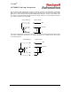
TrustedTM AN-T80004 Field Loop Configuration 24V 250R nominal Channel 250R 0V 250R nominal Channel output Channel output 0V 0V Cable earth and screen wires At either end of an I/O cable there may be a braid or heavy gauge green or green/yellow cable. This is the protective earth and should be bolted to safety earth. The chassis have a row of threaded holes for terminating these braids. On some I/O cables there may be a thin green wire.
TrustedTM AN-T80004 Field Loop Configuration Free Wire Cables I/O cables without FTA or VFTA plugs are available for most applications and are designed for connection to user-designed terminations (terminal blocks, multicore sockets etc.). These have ident markers on individual cores to show the function of each wire, with the ‘CORE’ text from the tables below. The wires are NOT colour coded and core colours will vary between batches or subcontracting manufacturer.
TrustedTM AN-T80004 Field Loop Configuration TC-206/506/208/508 (40 Channel Output) These cables have a short connection at the chassis end for field power supply, designed for a T8290 or T8297 Power Distribution Unit.
TrustedTM AN-T80004 Field Loop Configuration TC-216/516/218/518 (40 Channel Output with Integral Power) Power wires The integral power cables have the same I/O cores as the TC-206/506/208/508 cables above, but have field power connections wired through to the free end as shown here (one wire for each power group).
TrustedTM AN-T80004 Field Loop Configuration TC-602/702/604/704 (60 Channel Input) These cables are idented CH0 to CH61 with six (interconnected) 0V wires. Channels 41 to 60 are connected to two separate pins on the module socket as listed in the table above. This is because the 60 channel modules use a similar field PCB to the 40 channel modules but distribute two circuits to each channel instead of three. Channels 0 and 61 are internal reference channels and should not be connected.