
User Manual

I/O T
ermination Assembly
4
Industrial Control Services
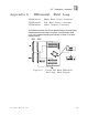
The unused pins of the connector are tracked to a screw terminal on
the PCB to allow the field cables and hoods to be grounded if required.
Module Operation
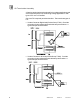
As shown below, pre
-
formed polarised I/O cables
are connected
between the I/O backplanes and ITA connectors
J1/J2/J3/J4/J6/J7/J8/J9. Field cables are connected to J5 and
common feed/returns and spare pin grounds are applied to connector
J10 (screw terminals). With a Screw Terminal ITA, connector J5
would consist of a set of dual row screw terminals.
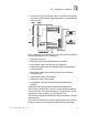
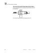
Pins 1 to 8 of the I/O Chassis 8
-
way connectors are wired one
-
to
-
one
with pins 1 to 8 of the 8
-
way connectors on the ITA. Each connector
on the ITA has pin identification shown on the l
egend of the ITA.
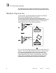
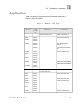
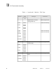
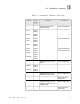
Cross
-
mapping between the 8
-
way connectors on the ITA and the
Varelco/Screw terminals is shown in the appendices. Where field
sensor power is provided on single ended ITAs, the tables in the
appendices show the field power connections and distribution.