
User guide

Monitored Guarded Output Modules
(T7481/81A, 84, and 88/88A)
12
(Issue 2)
Industrial Control Services
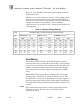
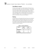
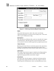
However, care should be exercised in applying the module to
small load devices.
Off
-
state test cur
rent (Leakage current ) of the output circuit
may prevent some load devices from turning off completely.
Table
2
lists the off
-
state voltages (worst case) for various load
ratings and module configurations. These should be
compared to the “
guaranteed off
” voltage for the load device
being applied.
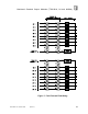
Table
2
. Off-
State Voltage Ratings.
Load
OFF State Voltage (nominal field voltage and shorted switch)
Rating
T7481/81A
(24 Vdc)
T7484
(110 Vac)
T7488/88A (120
Vdc)
(mA)
Single
Dual
Single
Dual
Single
Dual
5
na
2.6
na
3.7
na
na
na
12.8
na
18.3
10
na
1.4
na
2.0
na
na
na
6.8
na
9.9
20
4.7
.71
6.4
1.0
23.5
31.8
na.
3.5
na
5.2
35
3.0
.41
4.1
.6
14.8
20.8
17.5
2.0
24.4
3.0
50
2.2
.29
3.1
.43
10.8
15.5
12.8
1.4
18.2
2.1
100
1.2
.15
1.7
.21
5.7
8.4
6.7.
.71
9.8
1.0
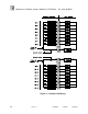
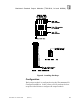
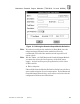
Field Wiring
Field wiring terminal blocks on the I/O chassis are used to
connect power sources and loads to the module. The terminal
blocks are located directly above and below the slot where t
he
module is installed. Each terminal block consists of ten #6
wire clamp screw terminals capable of holding two 12 AWG
wires.
Each module has separate power terminals for each output
group (group 1: channels 1
-
8, group 2: channels 9
-
16). The
two groups are electrically isolated from each other. Figure
6
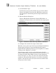
shows the proper field wiring for a single module and Figure
7
shows the field wiring for fault tolerant modules connected in
parallel.
This
module does not require a return connection from the
field power source. Do not connect any field wiring to
terminals A and D.
Note: