
User guide

Relay Output Modules
(T7446L, H)
2
Industrial Control Services
Module Operation
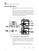
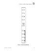
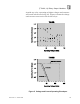
A block diagram of a typical relay output module is shown in
Figure
1
.
The processor modules send triplicated write data commands
to the output module over the I/O Safetybus. The processors’
addressing data and data write commands are voted by the
module (preventing I/O Safetybus failures upstream from the
module from affecting module operatio
n). The voted result is
then passed to the I/O bus interface logic.
Figure
1
. Block Diagram of a Relay Output Module.
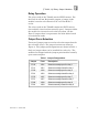
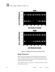
The voted output data from the I/O bus interface logic is then
used to drive the output circuits. Logic output drive signals
energize the coils of relays mounted on the printed circuit
board. Relay contacts provide dry
-
contact switching of load
devices.
When the output is logically turned on, the relay coil is
energized (closing the N.O.
contact), and when the output is