
User guide

(T7446L, H)
Relay Output Modules
PD
-
7017
Mar
-
06
11
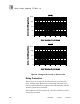
Fault Mode Jumper
The fault mode jumper is located behind the ID switch cover
in the lower left
-
hand corner of each I/O chassis. The position
of the fault mode jumper determines the module's response to
system level faults. The fault mode jumper’s position will
cause all output m
odules in the I/O chassis to either shutdown
(turn off all outputs) or to hold (hold the last state) after a
system level failure occurs. An example of a system level
failure is the failure of two processor modules.
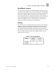
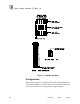
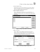
Keying
The I/O chassis can be physically keyed to prevent accidental
damage caused by inserting a module into a slot wired for a
different module type. Figure
7
illustrates how the slot keys
are installed on the I/O chassis slot field wiring connectors.
The slot key pos
itions for the relay output module are listed in
Table
2
. Both versions of the relay output module use the
same slot key positions.
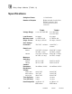
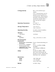
Table
2
. Slot Key Positions.
Module
Upper
Connector
Lower
Connector
T7446H
T7446L
17
2