
Manual

RTD Input Equipment
(T7432)
12
Industrial Control Services
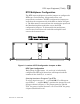
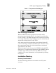
Figure
9
. Selecting American or European Type RTDs.
Selecting 2, 3 or 4
-
wire RTD Input Lead Config
uration.
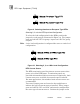
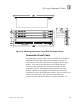
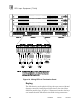
To select the lead configuration for the RTDs, position the
jumper for each group as illustrated in Figure
10
. The jumper
posts are labeled “JP7” for group 1 inputs and “JP8” for group
2 inputs.
2
-
wire lead configuration is configured the same as 4
-
wire lead
configuration.
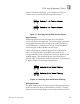
Figure
10
. Selecting 2, 3, or 4
-
Wire Lead Configuration.
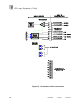
RTD Current Source
The RTD termination panel has sixteen current sources that
power each o
f the RTD inputs. Termination panels are
provided with standard 1mA current sources. Optionally, 5mA
current sources are available, but must be special ordered.
For most applications, the standard 1mA current sources are
recommended.
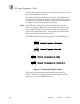
Two sets of jumper posts are located on the multiplexer to
indicate the type of current sources installed. These jumper
posts are labeled “JP1” and “JP9” and must be configured for
the same type of current sources. Position the jumper on the
Note: