ICS Regent+Plus ® PD-7023 Analog Input Modules 60 Hz Rejection and Fast Response (T7420A and T7420AF) Issue 1, March, 06 Analog input modules provide data input for a maximum of 16 field analog signals per module. Two types of modules are available: one for high noise immunity (60 Hz rejection) and one with low noise immunity (fast response). Features · Sixteen single-ended or eight differential voltage inputs.
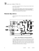
Analog Input Modules (T7420A, AF) prevent the controllers from receiving erroneous data from a faulty input module. Three analog input modules can be connected in parallel to obtain fault tolerant input sensing. In this triple module configuration, a failed module can be removed and replaced without interrupting the input signals. Module Operation A block diagram of the analog input module is shown in Figure 1. Figure 1. Block Diagram of Analog Input Module.
Analog Input Modules (T7420A, AF) The processor modules send triplicated read data requests to the analog input module over the I/O Safetybus. The processors’ addressing data and data read requests are voted by the module (preventing I/O Safetybus failures upstream from the module from affecting module operations). The voted result is then passed to the I/O bus interface logic.
Analog Input Modules (T7420A, AF) produces an I/O module error indication at the processor modules and a module fault indication at the I/O module. Each type of module has a unique identification code that is read by the controller. This code lets the controller know which type of module is installed in each I/O chassis slot and how to address that module and its points specifically.
Analog Input Modules (T7420A, AF) Figure 3. Analog Input Module.
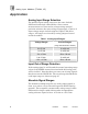
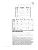
Analog Input Modules (T7420A, AF) Application Analog Input Range Selection The possible input voltage ranges are the same for both differential and single-ended modes. Since current measurements are converted to voltages using external precision resistors, the same voltage ranges apply. Choices of input voltage ranges include unipolar, bipolar, and offset ranges. All ranges are selected by setting jumpers located inside the module. Table 1. Analog Input Ranges.
Analog Input Modules (T7420A, AF) Sampling Speed The rate at which each of the analog input channels is sampled depends upon the mode of operation. Each channel is given a 225 msec time slot during the multiplexing process. During that time slot, the input voltage is connected to the measuring system, the measuring system is allowed to settle, the settled value is sampled (and held), and is then converted to a 12-bit value by an analog-to-digital converter. The channels are sampled in numerical order.
Analog Input Modules (T7420A, AF) Input Over Voltage Protection All analog inputs, regardless of mode and analog references (AREF1 and AREF2), are protected from over-voltages (these ranges are shown on page 27). Current Measurement Considerations Precision resistors external to the module are required to convert currents to voltages that can be measured directly by the module. The resistors can be mounted on field marshaling terminals or are provided using the appropriate analog input termination blocks.
Analog Input Modules (T7420A, AF) Table 2. Mode Selection. Jumper Single-Ended J251 n Differential J252 n J501 n n J502 n J503 J504 n J505 n J701 n Table 3. Input Range Selection.
Analog Input Modules (T7420A, AF) In differential mode, a 10K Ohm resistor is in series with each input line of each input analog channel pair. The capacitors are placed on the multiplexing side of the resistors. The filtering is then differential. There are four rows of eight pins labeled J506 and J507, for differential mode filtering install jumpers between rows J506 and J507 (for a total of eight jumpers). Frequency response data for the T7420A and T7420AF is provided on page 27.
Analog Input Modules (T7420A, AF) Figure 4. Analog Input Configuration Jumper Locations.
Analog Input Modules (T7420A, AF) Simplex Configuration Analog input modules provide a suitable interface to noncritical input signals. Although many of the circuits in the analog input modules are automatically tested and annunciated, some logic circuits and all of the field-side sensing circuits are simplex and non-tested. This simplex input configuration is illustrated in Figure 5. Figure 5. Simplex Analog Input Configuration.
Analog Input Modules (T7420A, AF) Figure 6. Fault Tolerant Analog Input Configurations. Field Wiring For field wiring details, refer to PD-7901 - I/O Termination Assembly.
Analog Input Modules (T7420A, AF) Keying The I/O chassis can be physically keyed to prevent accidental damage caused by inserting a module into a slot wired for a different module type. Figure 7 illustrates how the slot keys are installed on the I/O chassis slot field wiring connectors. The slot key positions for the analog input modules are listed in Table 4. Figure 7. Installing Slot Keys.
Analog Input Modules (T7420A, AF) Table 4. Slot Key Positions. Module Upper Connector Lower Connector T7420A 9 15 T7420AF 9 15 Configuration Each input module is configured using the WINTERPRET I/O Configuration Editor. In the editor, you will perform the three steps described below to configure the input module. 1) Set the Module Type: Position the cursor on the module slot you wish to define. Choose Set Module Type from the Edit Menu and select the appropriate analog input module from the list.
Analog Input Modules (T7420A, AF) Figure 8. Analog Input Module Definition. 3) Edit each point: Position the cursor on a Point definition and choose Edit from the Module Definition dialog box to define a name and description for each I/O point. In the Analog Input Point dialog, enter a tag name (up to 12 characters) and a description (up to 40 characters). The tag names are used in the application program to represent the value of the analog input in your control algorithms and interlocks. Figure 9.
Analog Input Modules (T7420A, AF) often you will want to scale the analog input values to a more convenient engineering unit number range. Scaling Analog Inputs The scaling function block is used to convert the raw 0 to 4095 units of the analog input to an engineering unit number. The result of this scaling conversion is usually stored in a shared variable register that you define in the shared variable editor.
Analog Input Modules (T7420A, AF) Programming Fault Tolerant Analog Inputs To program fault tolerant configurations using triplicated analog input modules, a midvalue element can be used as shown in Figure 11. Figure 11. Programming Fault Tolerant Analog Inputs. In this illustration, VALUE_A_NAME, VALUE_B_NAME, and VALUE_C_NAME represent the three analog inputs to be mid-value selected. ERROR_A_NAME, ERROR_B_NAME and ERROR_C_NAME are the error bits for the analog inputs.
Analog Input Modules (T7420A, AF) help you determine the frequency for checking the calibration of the modules in your installation. Calibration Methods Calibrating the analog input module requires that you connect calibration voltages to all of the analog input channels of the module and adjust the trimming potentiometers until the analog inputs read the correct calibration values.
Analog Input Modules (T7420A, AF) Calibration Preparation The module must be calibrated while connected to an I/O chassis of an operational Regent system. Important! During calibration, the analog input module will be disconnected from the actual field devices. Appropriate precautions should be taken to ensure that the disconnection of the field sensors does not pose a safety risk to plant personnel or process equipment.
Analog Input Modules (T7420A, AF) Figure 12. Analog Input Module Calibration Potentiometer Locations. The I/O extender module has jumper posts that allow you to connect or disconnect the I/O slot field wiring on the I/O chassis to the printed circuit board plugged into the I/O extender. During the calibration steps you will remove any jumpers installed on these posts in order to connect the DC voltage signal source to the analog inputs.
Analog Input Modules (T7420A, AF) Figure 13. I/O Extender Connections for Single-Ended Analog Input Calibration.
Analog Input Modules (T7420A, AF) Figure 14. I/O Extender Connections for Differential Analog Input Calibration. Important! Within each pair of jumper posts, make sure that you connect the voltage source to the jumper posts nearest the front of the I/O extender. Do not make any connections to the jumper posts nearest the I/O chassis backplane — these connect to the actual field wiring attached to the I/O slot terminals on the I/O chassis. Calibration Steps 1.
Analog Input Modules (T7420A, AF) 4. Connect the DC voltage signal source to the I/O extender jumper posts as shown in Figures 13 or 14. Use test clips as required to make the connections. 5. Remove the four screws on one side of the module and remove the printed circuit board from the module clamshell housing. 6. Install the printed circuit board into the I/O extender module. Allow the board to warm up for approximately one minute. 7.
Analog Input Modules (T7420A, AF) clamshell housing. Remove the I/O extender module from the I/O chassis and reinstall the calibrated module in the I/O chassis. The module’s red Fault indicator will be on until you perform a voted reset by pressing the Reset buttons on two of the Regent processor modules. After the voted reset is complete, the module’s green Active indicator should turn on. Table 5. Analog Calibration Voltages. Configured Voltage Range Offset Input Voltage Gain Input Voltage 0.00 to +10.
Analog Input Modules (T7420A, AF) Specifications Safetybus Power 1.85 load units Number of Inputs Eight differential or 16 single-ended (jumper selectable) Inputs Per Group Eight single-ended or four differential Ranges Voltage: Current: 0.00 to +10.00 volts -10.00 to +10.00 volts +1.00 to +5.00 volts 0.00 to +5.00 volts -5.00 to +5.00 volts (using external 250W resistors) 0.00 to +20.00 mA -40.00 to +40.00 mA +4.00 to +20.00 mA 0.00 to +20.00 mA -20.00 to +20.
Analog Input Modules (T7420A, AF) Out of Range Thresholds Over-range -10.00 to +10.00 volts: 0.00 to +10.00 volts: -5.00 to +5.00 volts: 0.00 to +5.00 volts: +1.00 to +5.00 volts: Under-range -10.00 to +10.00 volts: 0.00 to +10.00 volts: -5.00 to +5.00 volts: 0.00 to +5.00 volts: +1.00 to +5.00 volts: Expressed in volts: +10.30 min., +10.70 max. +10.30 min., +10.70 max. +5.15 min., +5.35 max. +5.15 min., +5.35 max. +5.12 min., +5.28 max. -10.30 min., -10.70 max. -0.30 min., -0.70 max. -5.15 min., -5.
Analog Input Modules (T7420A, AF) Operating Temperature 0° to 60° C (32° to 140° F) Storage Temperature -40° to 85° C (-40° to 185° F) Operating Humidity 0 to 95% relative humidity, non-condensing Vibration 10 to 55 Hz: ±0.
Analog Input Modules (T7420A, AF) Miscellaneous Input Circuit Specifications Function Signal Mode Value I leakage AI1 through AI16 — 50 nanoA (max.) Rin (re AGND) AI1 through AI16 — 100 Mohm (min.) Rin (re AREF2) AREF1 — 100 Mohm (min.) Rin (note 1) AI1 through AI16 SE 100 Mohm (min.) CMR (note 2) AI1 through AI16 SE 51 dB min. CMR (note 3) AI1 - AI16 SE 41 dB min. CMR (note 4) AI1 through AI16 SE 66 dB min.