
Instruction Manual


T6200 Controller Operation
5-5
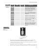
LED
NAME
COLOR
DESCRIPTION
ACT
(TOP)
Active Green This LED shows the Active/Standby status
of the Controller. When illuminated, the
Controller is “Active” and controls the
outputs. When a backup Controller is
used, either primary or backup can be
active, but not both of them.
NOR
Normal Green The LED shows the status of the watchdog
timer. The LED is illuminated when the
microprocessor is properly toggling the
watchdog timer.
EN1
Ethernet 1 Yellow This LED will flash when data is being
transmitted or received on Ethernet 1
EN2
Ethernet 2 Yellow This LED will flash when data is being
transmitted or received on Ethernet 2
COMM1
Communication 1 Green This LED will flash when data is being
transmitted or received on COMM 1 or
backup communication
COMM2
Communication 2 Green This LED will flash when data is being
transmitted or received on COMM 2
OUT
Outputs Red This LED illuminates when the outputs are
inhibited. This condition normally occurs
during power up. The backup control
board cannot be active if this LED is
illuminated.
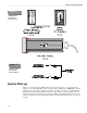
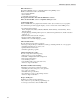
“Push to Activate”
Switc
h
Backup
Control Board
Primary
Control Board
If the primary board has a configuration in its memory, it will start the loop processing. If the primary
boards do not have configuration, the outputs will remain in their power-up reset condition.
At startup, the backup board's memory is always cleared, and the primary board transfers the configuration
to the backup board through the backup serial link.
During runtime operation, if a new configuration is downloaded, it automatically goes to the active board.
If the active board is the primary board, the backup board's memory is cleared, and the primary board
TABLE 5-1
Control
Board LEDs
Figure 5-3
Push to
Activate Switch