
Instruction Manual

Hardware Installation/Maintenance
3-28
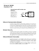
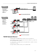
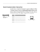
Serial Communication Connection
The T6200 includes two individual RS-232/RS-485 serial port connections (COMM 1 and COMM 2)
with RJ-45 connectors to facilitate serial communication. COMM 1 and COMM 2 are software
configurable for either RS-232 or RS-485. See Appendix C Modbus Interface RS-232 for COMM
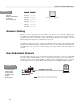
1 and COMM 2 RS-232/RS-485 Configuration. Note: RS-485 is not multidrop. Refer to Figure 3-8,
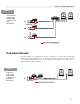
Figure 3-9, or Figure 3-10 for appropriate COMM 1 and COMM 2 connector location. Note: Non-
Redundant Dual Remote I/O Backplane (Figure 3-10) has only COMM 1 for the Primary and Second
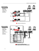
Control Board. Refer to Figure 3-26 for COMM 1 and COMM 2 connector pin assignments.
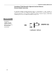
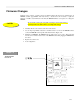
Pin Signal
1 NC
2 NC
3 TD (RS-232)/COMM-(RS-485)
4 SG (SIGNAL GND)/COM
5 SG (SIGNAL GND)/COM
6 RD (RS-232)/COMM+ (RS-485)
7 NC
8 NC
Pin 1
Pin 8
FIGURE 3-26
Serial
Communication
Connector