
Instruction Manual

Hardware Installation/Maintenance
3-24
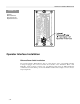
Operator Interface Installation
Ethernet/Power Cable Installation
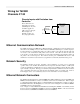
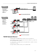
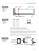
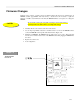
The Operator Interface Ethernet/Power cable is routed thru the center of the T6200 Controller
housing and plugged into connector J6 inside the Controller on the Termination Panel or I/O
Backplane. Refer to Figures 3-20 and 3-21. The Ethernet cable carries the 10Base-T Ethernet
communications and the 26Vdc power from the T6200 Controller. Refer to Figure 3-22 for connector
J6 pin assignments.
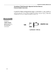
FIGURE 3-20
Internal
Ethernet/Power
J6 Connector for
O
p
erator Interface