
Instruction Manual

Hardware Installation/Maintenance
3-16
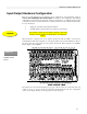
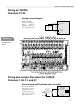
Wiring and Jumper Placement for T6200C
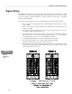
Channels 23-26
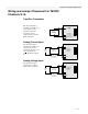
Two-Wire Transmitter
This wiring and jumper
placement is normally
used with isolated
two-wire transmitters
where the transmitter
power is supplied by the
Controller. Refer to
Figure 2-3.
Factory
Default
4-20 mA
Two-Wire
Transmitter
(Isolated)
+
-
SHLD
24 Vdc
Supply
mA Input
(reference to
common
through resistor)
+
-
T6200C Controller
1
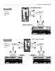
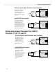
Current Inputs
This wiring and jumper
placement is normally
used with four-wire
current transmitters when
the power is not
supplied
by the Controller. Refer
to Figure 2-2.
4-20 mA
Transmitter
+
-
mA Input
(Isolated from
common)
+
-
T6200C Controller
1
Power
Source
Transmitter output
may be referenced
to common
SHLD
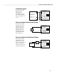
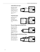
Analog Voltage Inputs
This wiring and jumper
placement is used for
voltage input. Refer to
Figure 2-1.
DC Voltage
Transmitter
+
-
+
-
T6200C Controller
1
Power
Source
Transmitter output
may be referenced
to common
DC Voltage Input
(Isolated from
common)
SHLD
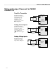
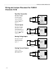
Analog Current Outputs
0-20mA (4-20mA)
Analog current outputs.
Refer to Figure 2-4.
4-20 mA or
0-20 mA
Receiver
(Isolated)
+
-
mA Output
+
-
T6200C Controller
1
SHLD
Circuit
Common