T6200 Ics triplex User’s Guide _____________________________________________________________________________________________________ T6200 Compressor Anti-Surge and Capacity Controller Issue 1 May 2004
Copyright 2004 ICS Triplex Contents of this manual may not be reproduced in any form without the written permission of ICS Triplex. Printed in the United States of America. Specifications are subject to change without notice. A/S VIEW MOPS, and T6200 are trademarks of ICS Triplex, Information furnished by ICS TRIPLEX is believed to be accurate and reliable. However, no responsibility is assumed by ICS TRIPLEX for its use. T6200 USER’S GUIDE ICS Triplex p/n 9001-0220 Issued May 2004 ICS Triplex, Inc.
T6200 User’s Guide TABLE OF CONTENTS SECTION 1 – PRODUCT OVERVIEW Design Structure.............................................................. ................................................................................ 1-3 Analog and Discrete Input/Output .................................. ................................................................................ 1-4 Line Power and Transmitter Power................................ ..............................................................
T6200 User’s Guide SECTION 4 - SOFTWARE INSTALLANTION The Micon OPC Server Compact Disc .......................... ................................................................................ 4-2 Install the Packet Driver Software .................................. ................................................................................ 4-2 Install the Micon OPC Server and Related Components............................................................................... 4-5 Ethernet Addresses..
T6200 User’s Guide SECTION 8 – CONFIGURATION Preface............................................................................. ................................................................................ 8-3 Configuration Studio........................................................ ................................................................................ 8-4 Running the FBD Configurator Workbench ................... ..........................................................................
T6200 6 User’s Guide
Product Overview 1 Section One Product Overview Design Structure 3 Analog and Discrete Input/Output 4 Line Power and Transmitter Power 5 System Security 5 On Line Diagnostics 6 Configuration Security 6 Controller Redundancy 6 Dual Non-Redundant Controller 6 1-1
Product Overview 1-2
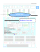
Product Overview PRODUCT OVERVIEW The T6200 Controller is made up of two parts: The Operator Interface and the T6200 Controller. The Operator Interface with the Windows CE platform enables complete interaction with the T6200 Controller. Through the touch screen and LCD display users can change setpoints, outputs, start/stop devices, scroll through trends, or acknowledge alarms.
Product Overview FIGURE 1-1. T6200 Unit Controller Analog and Discrete Input/Output Analog inputs can be either current or voltage. High common mode (200 Volts) amplifiers are utilized. Each input has a separate input amplifier. Also, each two wire transmitter input (4-20mA) is provided with a separate internal 24 volt regulator. Analog outputs source up to 20 milliamperes to the user’s receiver (load). Most discrete inputs are opto-isolated (refer to specifications).
Product Overview configured as frequency/pulse inputs. Discrete outputs are transistor configurations. A separate internal 24 volt regulator is supplied for each input/output. The internal I/O section of the Controller accommodates 32 I/O points. Refer to Table 1-1 for I/O channel assignment information. TABLE TABLE1-1 1-1..
Product Overview diagnostics and also monitors the status of the other control board which provides for a reliable transfer and redundancy scheme. On Line Diagnostics The T6200 Controller has on-line diagnostics designed to identify failures quickly. On all (primary and backup) operator interfaces, highways, local communications, the Controller run diagnostics on a continuous basis. These routines continuously check the status of critical device functions to detect failures.
Input/Output Circuit Description 2 Section Two Input/Output Circuit Description Analog Voltage Inputs 3 Analog Current Inputs 4 Analog Current Outputs 4 Isolated Discrete Inputs 6 Discrete Inputs with Excitation from Controller 6 Discrete Outputs 8 Discrete Outputs with Internal Power 8 Discrete Outputs with External Power 9 Active/Standby Logic 9 2-1
Input/Output Circuit Description 2-2
Input/Output Circuit Description INPUT/OUTPUT CIRCUIT DESCRIPTION Each control board in the T6200 Controller incorporates the µP, memory, communications and I/O circuitry. Separate I/O modules are not required. Analog Voltage Inputs Up to 20 channels in the T6200-C Controller can be configured with field changeable jumpers for voltage inputs.
Input/Output Circuit Description Termination Panel Primary Control Board 200 Volt Common-mode Amplifier 1A FIGURE 2-1 100V Analog Voltage Input Analog Switch Programmable Gain Amplifier To ADC 1A 100V Analog Voltage Input Backup Control Board 200 Volt Common-mode Amplifier 1A 100V Analog Switch Programmable Gain Amplifier To ADC 1A 100V Analog Current Inputs The current input is similar to the voltage input with 250 ohm resistor across the amplifier inputs.
Input/Output Circuit Description Termination Panel FIGURE 2- 2 200 Volt Common-mode Amplifier Primary Control Board Analog Switch Programmable Gain Amplifier Analog Current Input To ADC 4-20 MA Input 200 Volt Common-mode Amplifier Backup Control Board Analog Switch Programmable Gain Amplifier To ADC FIGURE 2- 3 Primary Control Board Termination Panel 1A Two-Wire Transmitter Input Voltage Regulator with short-circuit protection 24 VDC 100V Analog Switch 1A 100V Two-Wire Transmitter Input
Input/Output Circuit Description Termination Panel Primary Control Board FIGURE 2-4. +25.2V Voltage to Current Converter DAC Analog Current Output 125mA 50 OHM From Microprocessor Reset Analog Current Output Inhibit from Figure 2-9 Active from Figure 2-9 Primary Control Board +25.
Input/Output Circuit Description Termination Panel FIGURE 2- 5. Primary Control Board 1A Input to Microprocessor 100V Isolated Discrete Input 1.8K 1A 4.7K 100V Power Backup ControlBoard 1A Input to Microprocessor 100V 1.8K 1A 4.7K 100V FIGURE 2-6. Termination Panel Primary Control Board 1A 100V Discrete Input with Excitation from Controller 1A Voltage Regulator 24 VDC Input to Microprocessor 1.8K 4.
Input/Output Circuit Description Discrete Outputs The T6200-C Controller can be configured for up to eight discrete outputs. The T6200-D Controller can be configured for up to 28 discrete outputs. A 100 volt transient absorber is connected on each terminal to protect the output transistor and to prevent arching between conductors on the circuit board. Each terminal is protected with a one ampere fuse. The output transistor in the standby (not ACTIVE) control board is always open.
Input/Output Circuit Description Discrete Outputs with External Power In reference to Figure 2-8, the discrete transistor output with an external power source can sink up to 0.25 amperes continuously and one ampere momentarily. The maximum voltage that can be applied continuously is 38 volts DC. The return (-) of the external power source must be connected to the “-” input or “-” power terminal of the T6200 Controller. Termination Panel FIGURE 2-8.
Input/Output Circuit Description FIGURE 2-9 Active/Standby Logic Termination Panel Primary Control Board Active ACT LED Inhibit Power Up Reset System Fail OUT LED Activate switch Backup Control Board Active ACT LED Inhibit Power Up Reset System Fail OUT LED Activate switch 2-10
Hardware Installation/Maintenance 3 Section Three Hardware Installation/Maintenance Site Selection Considerations 3 Access Considerations 3 T6200 Unit Automating System Mounting 4 T6200 Controller Electrical Power Wiring 6 T6200R Subrack Electrical Power Connection 8 Input/Output Hardware Configuration 9 Signal Wiring 10 Wiring and Jumper Placement for T6200-C Channels 1-8 12 Wiring and Jumper Placement for T6200-C Channels 9-16 13 Wiring and Jumper Placement for T6200-C Channels 17-22, 31, and 32 14 Wiri
Hardware Installation/Maintenance 3-2
Hardware Installation/Maintenance Hardware Installation/Maintenance ` Site Selection Considerations The T6200 Controller requires following conditions during normal operation: 32 to 122º F (0 to 50º C) 5 to 96% Relative humidity Protection from direct contact with water, chemicals, and conductive dust. Protection from exposure to sulfur compounds, acid, other corrosive or reactive vapors or fumes, dust, and lint.
Hardware Installation/Maintenance The control boards slide out the front of the unit. To ensure a proper viewing angle, the Controller should be installed approximately 64 inches (1.6 m) above the floor. Outdoor installation is not recommended. However, for outdoor installations, the face of the Controller should be shielded from direct sunlight, since bright light produces a poor display contrast.
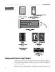
Hardware Installation/Maintenance FIGURE 3-1. T6200 Mounting Dimensions 4.30 [109] 2.74 [69] 2.68 [68] FIGURE 3-2. T6200 Controller Panel Cutout Dimensions 1.72 [44] MIN OPERATOR INTERFACE PANEL CUTOUT 5.44 [138] 5.95 [151] 5.50 [139] 1.
Hardware Installation/Maintenance FIGURE 3-3 Remote I/O Terminal Panel Mounting Dimensions T6200 Controller Electrical Power Wiring The guidelines below should be followed when wiring the power to the T6200 Controller: The maximum wire size is 16 AWG stranded. All wiring should be multi-stranded annealed copper with insulation that meets the requirements of all applicable electrical codes. AC power wiring should be run in a separate conduit from the T6200 Controller power and the I/O.
Hardware Installation/Maintenance FIGURE 3-4 T6200R Subrack Mounting Dimensions Figure 3-5 shows the internal power distribution for the T6200 Unit Automation System. Connect 26 Vdc (18-32 Vdc) power to the 26V PRI (Primary) terminals and to the 26V SEC (Secondary) terminals. There is a jumper (W1) on the T6200 Termination Panel that connects the minus side of the 26 volt supply to earth ground. This jumper may be cut if the power source is referenced to earth ground somewhere else in the system.
Hardware Installation/Maintenance FIGURE 3-5 Internal Power Distribution T6200R Subrack Electrical Power Connection Once the T6200R Subrack is mounted, plug the included external power supply’s DC power cord into the matching power jack on each of the Ethernet Hub’s rear panel. The Ethernet Hub shelf may be removed to connect the power. Plug each of the power supply’s transformers into an AC receptacle that is six feet (two meters) or less away. The green “Pwr” LED should light up.
Hardware Installation/Maintenance Input/Output Hardware Configuration There are several different ways the hardware can be configured for each input/output. Refer to Section Two Input/Output Circuit Description for details on each configuration. The different configurations are achieved by the placement of jumpers (shorting bars) on a multi-pin headers located on the printed circuit board. Each channel has a separate header and can be configured independently.
Hardware Installation/Maintenance Signal Wiring Individually shielded wires are not required (except for frequency inputs). Twisted pairs and overall cable shields are recommended. Each multipair cable should contain a few pairs of spare wires. Shields and unused conductors should be terminated to ground at Controller end only. Refer to appropriate Wiring and Jumper Placement. The following general guidelines apply to all signal wiring discussed in the following paragraphs.
Hardware Installation/Maintenance FIGURE 3-9 Redundant Remote I/O Termination Panel FIGURE 3-10 Dual Non-Redundant Remote I/O Termination Panel 3-11
Hardware Installation/Maintenance Wiring and Jumper Placement for T6200C Channels 1-8 Two-Wire Transmitter T6200C Controller This wiring and jumper placement is normally used with isolated two-wire transmitters where the transmitter power is supplied by the Controller. Refer to Figure 2-3.
Hardware Installation/Maintenance Wiring and Jumper Placement for T6200C Channels 9-16 Two-Wire Transmitter T6200C Controller This wiring and jumper placement is normally used with isolated two-wire transmitters where the transmitter power is supplied by the Controller. Refer to Figure 2-3.
Hardware Installation/Maintenance Discrete Inputs with Excitation from Controller This wiring and jumper placement is for discrete (On/Off) inputs. The Controller supplies 24 VDC power for the input. Refer to Figure 2-6. Alternate Open Collector Transistor + T6200C Controller Discrete Input (24 Vdc/5 mA 1 excitation) - Circuit Common Contact Isolated Discrete Inputs This wiring and jumper placement is for discrete (On/Off) inputs.
Hardware Installation/Maintenance Frequency Inputs This wiring and jumper placement is for a frequency/pulse preamplifier input with the Controller supplying the power (Channel 22,31 and 32). T6200C Controller + 24 Vdc Supply OUT - Discrete Input COM SHLD (Circuit Common) PWR Frequency/Pulse Preamplifier or other Discrete Device 0-25KHz only for Channels 22, 31 & 32 1 Discrete Outputs with Internal Power This wiring and jumper placement is for discrete (On/Off) outputs.
Hardware Installation/Maintenance Wiring and Jumper Placement for T6200C Channels 23-26 Two-Wire Transmitter This wiring and jumper placement is normally used with isolated two-wire transmitters where the transmitter power is supplied by the Controller. Refer to Figure 2-3.
Hardware Installation/Maintenance Wiring for T6200C Channels 27-30 Analog Current Outputs 0-20mA (4-20mA) Analog current outputs. Refer to Figure 2-4. Channels 27-30 do not have jumper placements. T6200C Controller + mA Output + 4-20 mA or 0-20 mA Receiver (Isolated) - - Circuit Common SHLD FIGURE 3-11 T6200D Control Board Wiring and Jumper Placement for T6200D Channels 1-26, 31, and 32 Discrete Input with Excitation from Controller This wiring and jumper placement is for discrete (On/Off) inputs.
Hardware Installation/Maintenance Isolated Discrete Input This wiring and jumper placement is for discrete (On/Off) inputs. The discrete inputs are isolated from other circuits and the external power for the input is either 18-32 Volt AC or DC. Refer to Figure 2-5.
Hardware Installation/Maintenance Wiring for T6200D Channels 27-30 Discrete Inputs with Excitation from Controller These channels are for placement is for discrete (On/Off) Inputs only. The Controller supplies 24 VDC power for the input. Refer to Figure 2-6 Channels 27-30 do not have jumper placements. T6200D Controller Discrete Input + (24 Vdc/5 mA excitation) Alternate Open Collector Transistor Contact - Circuit Common Ethernet Communication Network The T6200 Controller uses IEEE 802.
Hardware Installation/Maintenance FIGURE 3-12 Ethernet ENET1 and ENET2 Connector Pin Assignments Pin 1 2 3 4 5 6 7 8 Signal TXD+ TXDRXD+ NC NC RXDNC NC Pin 1 Pin 8 Network Cabling Ethernet is used as the high-speed wire media to provide the control network communication capabilities for the T6200 Controller systems. Typically, the control network is an isolated Ethernet network that provides communication between the T6200 Controller and workstations.
Hardware Installation/Maintenance FIGURE 3-14 Non-Redundant Network with Multiple T6200 Controllers and Dual Workstations Redundant Network Network redundancy for communication security is provided by a secondary hub and cables that establish a secondary network identical to the primary network. The secondary network is connected to the redundant communications port of each workstation and Controller, and is connected to a separate hub/switch. Refer to Figure 3-15.
Hardware Installation/Maintenance FIGURE 3-16 Redundant Network with Multiple T6200 Controllers and Redundant Workstations FIGURE 3-17 Redundant Network with Multiple T6200 Controllers Mounted in a T6200R Subrack and Redundant Workstations 3-22
Hardware Installation/Maintenance FIGURE 3-18 Non-Redundant Network with Single Dual T6200 Controller and Single Workstation FIGURE 3-19 Redundant Network with Multiple Dual T6200 Controller and Redundant Workstations T6200R Subrack Ethernet The Ethernet Hubs on the T6200R Subrack are usually connected as shown in Figure 3-17. If the workstation is not part of an existing network, connect the workstation to port eight on the hubs. Set the Up-Link switch to “Normal”.
Hardware Installation/Maintenance FIGURE 3-20 Internal Ethernet/Power J6 Connector for Operator Interface Operator Interface Installation Ethernet/Power Cable Installation The Operator Interface Ethernet/Power cable is routed thru the center of the T6200 Controller housing and plugged into connector J6 inside the Controller on the Termination Panel or I/O Backplane. Refer to Figures 3-20 and 3-21. The Ethernet cable carries the 10Base-T Ethernet communications and the 26Vdc power from the T6200 Controller.
Hardware Installation/Maintenance FIGURE 3-21 Operator Interface Internal Ethernet/Power Cable Installation FIGURE 3-22 Operator Interface J6 Connector Pin Assignments Pin 1 2 3 4 5 6 7 8 Signal TXD+ TXDRXD+ +26V PRI +26V SEC RXDCOM COM Pin 1 Pin 8 Operator Interface Attachment to T6200 Chassis The Operator Interface is attached to the T6200 Chassis by four screw collars.
Hardware Installation/Maintenance Standalone T6200 Controller Operator Interface Ethernet External Cable Connection For Standalone T6200 Controller applications where no communications to other controllers or workstations are required, the T6200 Controller ENET1 connector may be connected directly to the OI (Operator Interface) connector with a short Ethernet crossover cable (ICS Triplex p/n 6009-0030) eliminating the necessity of an Ethernet hub. Refer to Figure 3-24.
Hardware Installation/Maintenance Firmware Changes Firmware is the software, operating system, and function library that has been programmed into an EPROM (erasable programmable read-only memory). Should it become necessary to update the firmware or install a custom firmware in the field, the EPROM will have to be replace. To change the EPROM: The Controller contains parts susceptible to damage by electrostatic discharge. Normal precautions should be taken to avoid high static voltages.
Hardware Installation/Maintenance Serial Communication Connection The T6200 includes two individual RS-232/RS-485 serial port connections (COMM 1 and COMM 2) with RJ-45 connectors to facilitate serial communication. COMM 1 and COMM 2 are software configurable for either RS-232 or RS-485. See Appendix C Modbus Interface RS-232 for COMM 1 and COMM 2 RS-232/RS-485 Configuration. Note: RS-485 is not multidrop. Refer to Figure 3-8, Figure 3-9, or Figure 3-10 for appropriate COMM 1 and COMM 2 connector location.
Software Installation Section Four 4 Software Installation The Micon OPC Server Compact Disc 2 Install The Packet Driver Software 2 Install the MICON OPC Server and Related Components 5 Ethernet Addresses 7 4-1
Software Installation Software Installation Instructions for the installation of the MICON OPC Server and a sample OPC Client software on Microsoft Windows XP. The Micon OPC Server Compact Disc The MICON OPC compact disc contains the Micon OPC Server, a sample OPC Cliente. The setup program for the MICON OPC Server software and the sample OPC Client software are located in the “MICON” folder. Create a directory "C:\MICON" on the installation computer.
Software Installation Figure 4-.
Software Installation Figure 4-3 Local Area Connection Properties Window Figure 4-4 Select Network Component Type Window Open the “Locate File” window: 4-4 Select “Browse” (Figure 4-6) Locate the "\ndisnt” folder on the installation CD Select “OK”
Software Installation Figure 4-5 Select Network Protocol Window Figure 4-6 Install From Disk Window Windows will select “OEMSETUP.INF” in the “File name:” field as shown in Figure 4-7. Select “Open” to install the NDIS3P2K.INF driver. The “Virtual Packet Driver” will be highlighted as shown in Figure 4-8. Select “OK” to complete the driver installation. Install the MICON OPC Server and Related Components Install the MICON OPC Server and related components. Execute the file "\MICON\Setup.
Software Installation Figure 4-7 Locate File Window Figure 4-8 Select Network Protocol Window Figure 4-9 InstallShield Selfextracting EXE Window 4-6 Select “Yes”. This will open the “Readme Information” window (Figure 4-10). Select “Next”. This will open the “Setup Complete” window (Figure 4-11).
Software Installation Figure 4-10 Readme Information Window Figure 4-11 Setup Complete Window Ethernet Addresses Edit or create a file "C:\MICON\devlist.txt" using Notepad or some other text editor.
Software Installation Primary Control Board Ethernet Address Backup Control Board Ethernet Address UC254,00:08:9A:D2:05:02,00:0D:9A:D2:05:02, UC255,00:08:9A:D2:06:02,00:0D:9A:D2:06:02, BAK ID from I/O Backplane PRI ID from I/O Backplane T6200 Controller Name The strings are separated by a comma. The first string is the name for the T6200 Controller. The second string is the Ethernet address for the primary control board and the third string is the Ethernet address for the backup.
T6200 Controller Operation 5 Section Five T6200 Controller Operation Push to Activate Switch 5 System Start-up 6 Replacing Control Boards 6 Loading Controller Configuration 8 Watchdog Timer 8 5-1
T6200 Controller Operation 5-2
T6200 Controller Operation T6200 Controller Operation The redundant T6200 Controller consists of two identical control boards, primary and backup, and one termination panel. Refer to Figure 5-1. The primary control board is always on the left and the backup is always on the right. Normally, the primary board is the active board and the backup board is the standby board. These roles may be reversed. When the backup board is active, it transmits a “Backup Active” alarm to the host.
T6200 Controller Operation FIGURE 5-1 T6200 Primary and Backup Control Boards Figure 5-2 T6200-C Active and Standby Current Outputs System Start-up When power is first applied, the T6200 Controller forces the analog outputs to zero and the discrete outputs to open. Next, the T6200 Controller starts the self-test and flashes the COMM LEDs. After the self-test has been successfully completed, the primary board will become active. The OUT LED will illuminate on the backup board during this wait period.
T6200 Controller Operation TABLE 5-1 Control Board LEDs LED NAME COLOR DESCRIPTION ACT (TOP) Active Green NOR Normal Green EN1 Ethernet 1 Yellow EN2 Ethernet 2 Yellow COMM1 Communication 1 Green COMM2 Communication 2 Green OUT Outputs Red This LED shows the Active/Standby status of the Controller. When illuminated, the Controller is “Active” and controls the outputs. When a backup Controller is used, either primary or backup can be active, but not both of them.
T6200 Controller Operation transfers the configuration to the backup board through the backup serial link. The standby primary board’s memory cannot be cleared during runtime operation without removing the board. To transfer a configuration from a backup board to a primary board, the primary board must be removed (unplugged) and reinstalled, clearing the memory at the same time (see Replacing Control Boards below).
T6200 Controller Operation Watchdog Timer The microprocessor toggles the watchdog timer at least once every 100 milliseconds. If the watchdog timer is not toggled within this time period, the watchdog timer will reset the microprocessor. If the board is on standby, the outputs will be disabled. If the board is active, control will be transferred to the backup board.
T6200 Controller Operation 5-8
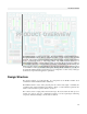
HMI-6200 Operator Interface Section Six 6 HMI-6200 Operator Interface Preface 2 Overview of HMI-6200 Features 3 Event Information Processing 5 Display Layout 11 General Display Description 14 Graphic Displays Configuration 17 HMI Example – Single Stage Compressor 18 Adaptation of Pre-Defined Displays 21 Surge Curve Screens 25 Custom Graphic Screens - 26 Configuring the Security System 27 Communications 30 Downloading the Updated Application 34 6-1
HMI-6200 Operator Interface HMI-6200 OPERATOR INTERFACE Preface To be effective in a small (5.7” P/PC size) footprint, the operator interface must be ergonomically pleasing and comfortable to the user.
HMI-6200 Operator Interface Overview of HMI-6200 Features A standard option of the T6200 Unit Automation System is to incorporate an integral 5.7 inch P/PC based full-featured human-machine interface – HMI-6200.
HMI-6200 Operator Interface OPC Client/Server – The build-in CE OPC Server is compatible with the StrongARM processor Enables communication with control modules - Open systems OPC link - Server identifier - Configurable data update rate If an operator interface other than the HMI 6200 is selected make sure that the OPC server is compatible with its processor. Comprehensive GUI – Based on WEB Studio, the graphical user interface offers object oriented easy to use graphics.
HMI-6200 Operator Interface Event Information Processing The following describes the information structure for alarm and alert handling and for trend and historical recording Alarm and Alert Definition – The T6200 includes comprehensive detection and notification of alarms and alerts. Alarms are defined as conditions which require user acknowledgement; alerts are records of actions/conditions for which operator acknowledgement may or may not be specified (Ack is configuration selectable).
HMI-6200 Operator Interface FIGURE 6-2 Alerts - Summary Display Historical Alarm and Alert Display The Alarm/Alert History display provides for means of viewing past Alarm and Alert events. Historical data can be retrieved with convenient date/time selection buttons.
HMI-6200 Operator Interface Dynamic Trending Module – The HMI-6200 trend capability provides for viewing of real-time and historical data. A trend display format, with up to six plots, is included. Trend Configuration – The contents of the Trend and the Trend History display are defined by trend window templates as shown below.
HMI-6200 Operator Interface 6-8
HMI-6200 Operator Interface Trend Display – The trend display is presented in the popular strip chart recorder format. FIGURE 6-6 On-Line Trend Display Historical Tend Display The Trend History display provides for a comprehensive means of viewing process and calculated data over periods of time.
HMI-6200 Operator Interface FIGURE 6-7 Trend History Date/Time Selection 6-10
HMI-6200 Operator Interface Display Layout Preformatted displays provide the basic operations interface for: compressor/turbine control, continuous process control, batch/sequence control, SCADA alarms, trends, etc. Information is presented in an easily understood manner. The operational displays are organized into a structural hierarchy consisting of overview(s), graphics, face-plates, etc. Displays are called up through a simple menu bar procedure.
HMI-6200 Operator Interface HMI-6200 Header and Footer Template The Web Studio screen editor allows you to create a variety of windows and dialogs which feature user inputs by screen selection and touch pad. The following relates to the HMI-6200’s process display access formats that are pre-defined by a standard Header and Footer template.
HMI-6200 Operator Interface - UAM displays access - Alarm Summary/History display access - Alert Summary/History display access 6-13
HMI-6200 Operator Interface General Display Description “Home” Display – The “Home” display typically provides for an overview presentation of the compressor performance with an “at a glance” identification of off-normal and alarm conditions. The operator can select directly subdisplays (Graphics, Face-Plates, Diagnostics and Operation etc.) from this display to bring details into view.
HMI-6200 Operator Interface Trend Display – The trend module displays analog and discrete points on trend of any tagged system variable. The trend display can contain up to six variables (plots) – continuously updated. Plot colors, scale (Min, Max), Cursor Value and time span are selectable. Curve type can either be X/t or XY. One can store the trend points in a history file for data collection and display.
HMI-6200 Operator Interface FIGURE 6-9 Workspace Window Task Tab Scheduler – Critical and control related timed-tasks normally reside in the T6200 control module(s). However, timed tasks for reports, supervisory recipes, trend and math are typically handled by the HMI-6200 Scheduler module. The timed-task module (scheduler) supports reports, logs, recipes and general actions (math and logic functions). It provides for the scheduling, definition and detection of timed tasks.
HMI-6200 Operator Interface Graphic Displays Configuration The HMI-6200 graphics software is a runtime-only version of the workstation PC graphics. All configurations of graphic displays are made using a workstation PC and then downloaded to the HMI6200 P/PC Operator Interface. Once in run-time mode, the user is able to execute all runtime functional dynamics that have been added/defined during configuration. Powerful HMI Visualization A complete set of drawing and animation tools is furnished.
HMI-6200 Operator Interface HMI Example – Single Stage Compressor The following shows an example of a T6200 Compressor Unit HMI for single stage centrifugal machines. The HMI is designed to facilitate operation at all levels. It permits simplified access to the unit, provides a logical display hierarchy, and a choice of navigation for easy interaction with the process.
HMI-6200 Operator Interface FIGURE 6-14 Compressor FacePlate Screens and Aux Displays provide for traditional operation convenience A/S Face-Plate Display/Control Capacity Face-Plate Display/Control LS Face-Plate Display/Control LSE Face-Plate Display/Control Lube Oil Display/Control Seal Gas Display/Control 6-19
HMI-6200 Operator Interface From operator displays to maintenance screens to engineering displays the HMI-6200 covers the full interface spectrum. This color LCD display represents an HMI with full DCS/SCADA capabilities. It provides a complete “window” on the process by which one can operate/control, maintain and manage the process unit.
HMI-6200 Operator Interface FIGURE 6-17 Maintenance Screens facilitate process and control diagnostics Operation Status Display Process Status Display Load Share Diagnostic Display Load Efficiency Diagnostic Display Loop Tuning Display/Entry Interlock Display Adaptation of Pre-Defined Displays The general HMI-6200 operator interface consists of preformatted displays. These displays are structured into overview(s), graphics, face-plates, trend, etc.
HMI-6200 Operator Interface interface that allows for easy customization and adaptation to the specific process/plant configuration. Besides adaptation at the time of system set-up, some display configuration is usually done later on. System Requirements The HMI-6200 operator interface is based on Web Studio. To develop/adapt an application with Web Studio software, the following hardware and software is recommended for the Host computer...
HMI-6200 Operator Interface Class Tags Loop tags – PV, SP, Out, Mode – are defined in a tag format called “classes”. This permits a high degree of encapsulation. When a class-type tag is created, it does not contain a single value, but a set of values associated with the loop. When a new loop is created, it is recommended to follow the predefined class type definition. Database Exercise In the development computer Workspace window, select the Database tab.
HMI-6200 Operator Interface Changing/Expanding Screens Before changing and/or expanding screens, you should consider the pre-defined structure of the application screens. For new screens, you can use existing screens (including the Standard screen), saving it under different names. To update/change an existing screen, insert/change the objects in the window between the header and footer. It is not recommended to change the header or footer arrangement itself.
HMI-6200 Operator Interface Surge Curve Screens FIGURE 6-20 Surge CurveOp Point Display: X/Y Map SLL Configuration below - - Surge Curve Configuration: The Surge Limit Line (SLL) is arranged in a lookup table format with linear vector interpolation. Up to 20 points can be defined. The X points define the domain input – Hp,sim. The Y points define the range (output) – Q2,sim. Click on Edit Mode Enable check.
HMI-6200 Operator Interface Custom Graphic Screens While the pre-defined operating displays that are provided with the HMI-6200 operator interface meet the needs of some users, many still wish to create displays that are specific to their respective unit operations. Like the pre-defined displays, user-defined graphic displays are constructed via the Web Studio Object Toolbar and by importing symbols from the Library.
HMI-6200 Operator Interface Configuring the Security System The Security folder allows you to define Groups and Users as well as their access privileges to Web Studio tools and to the application. Through the Database tab, you can tailor Groups and Users to your security needs. FIGURE 6-22 Workspace Window Task Tab Selection of Security - Password: __________ is pre-defined as the Main Password.
HMI-6200 Operator Interface - Maintenance Group: Double-click Maintenance, enter the Password, and the Group Account window will open. FIGURE 6-24 Security Group Account Window Maintenance Group In this window you enable/disable the Maintenance Group operations and you set the range levels. Verify that the Security Levels and Access are defined in accordance with your application requirements. - Operations Group: Double-click Operations, enter the Password, and the Group Account window will open.
HMI-6200 Operator Interface - Users: Double-click the User Account labels of the Security System window, enter the Password, and the individual User Account windows will open. FIGURE 6-26 User Account Windows - Dev1 - Maint1 - Op1 In these windows, you create and maintain accounts for application users. Verify (and if needed redefine) the application users that will be in each group in the Group Account list. Users can also be accessed by selecting the User option under Insert on the Main Menu Bar.
HMI-6200 Operator Interface Communications OPC Communication The Web Studio OPC Client module communicates with the MICON OPC Server module using the OPC Data Access Standard. The Tag Names passed between the OPC Client and Server are defined under OPC in the Comm tab. FIGURE 6-28 Workspace Window Comm Tab Selection of OPC Sheets OPC Worksheets: Double-click on the desire OPC item (GEN, AI/AO, Stage) to open the OPC Client worksheets.
HMI-6200 Operator Interface FIGURE 6-30 OPC Worksheets: Stage#1 Parameters Verify that all dynamic tags required by the HMI-6200 Operator Interface are listed under Tag Name and are associated with the correct OPC Server item. Also, make sure that tags are not selected as Scan Always unless the specific tags require continuous scanning, such as Alarm/Alert related tags. Tag Names are obtained from the Database (double-click on Tag Name column).
HMI-6200 Operator Interface WEB Communication: Web Studio allows you to save your application screens in HTML format and export them to Internet Browsers (Internet Explorer). You need to set the parameters in the Web tab in the Program Settings dialog window and save the screens which you desire for Web communications as HTML (menu File – Save as HTML). Caution: The Web Pages generated by the Save As HTML function are independent of the screen file they were generated from.
HMI-6200 Operator Interface Once all the settings are correct, turn on the Web Server then run the application. With both of these running you should be able to use Internet Explorer to connect to the application By selecting the URL (http:////.html). A prompt for a username and password will appear, enter one of the username and passwords from the security section.
HMI-6200 Operator Interface Downloading the Updated Application After the adaptation of the pre-defined displays is completed, connect the development computer to the controller operator interface via a direct HMI Crossover Ethernet cable or via the controllers’ Primary Ethernet connection (T6200 rear termination panel, Ethernet 1).
HMI-6200 Operator Interface Development Computer Arrangement Make sure that the operator interface is properly connected to the development computer. Network TCP/IP Properties Adaptation Setting > Control Panel > Network. You will need to change the IP address on the development computer only if the first three digits of the development computer's IP address do not exactly match the first three digits of the Operator Interface's IP address.
HMI-6200 Operator Interface digits of the Operator Interface's IP address. Then press Connect. The Status line will confirm the connection as shown above. Note: After completion of application downloading, do not forget to return the radio button selection from Network IP to Local.
Control Primer 7 Section Seven Control Primer Proportional (P) Action 5 Integral (I) Action 8 Derivative (D) Action 8 Proportional-plus-integral (PI) Action 9 Proportional-plus-derivative (PD) Action 10 Proportional-plus-integral-plus-derivative (PID) Action 11 Interactive and Non-interactive Control 12 Deadtime 13 Cascade Control 14 Ratio Control 16 Damping 16 7-1
Control Primer 7-2
Control Primer Control Primer Controllers are used by the process industries as well as other industries. They are usually used, among other things, to improve accuracy, efficiency, safety, environmental, and to automate, ie., when the controller takes action it has a way to measure the result and then modify the action. Most of these controllers are used in a closed-loop with negative feedback. Sometime they are used in an open-loop, normally referred to as feedforward control.
Control Primer Figure 7-1. A Simplified Feedback Controller in a Process Loop The input block represents the input signal conditioning circuits. The setpoint is the controller's reference. The setpoint is usually set by an operator, but sometimes the setpoint is the output of another controller. The comparator compares the input and setpoint and the difference is called the error. This error is passed on to the calculator.
Control Primer Proportional (P) Action The proportional action has a linear response. The controller output response will have the same shape as the controller error response but the amplitude may be different and it may also have an offset. Refer to Figure 7-2. Sometimes the proportional action is expressed in percentage and is called proportional band (PB).
Control Primer Figure 7-2 Proportional (P) Control Action The advantages of the proportional action are: it is simple, easy to tune, and has a rapid response. The disadvantage is that it has an offset. Using the expression in Figure 7-2 and substituting e with expression 7-1 yields the expression for m the manipulated output: m=K(r-c)+b (7-3) Figure 7-3 is an example of how the offset can be shown by repeatedly solving for the manipulated controller output (m) in expression 7-3.
Control Primer Figure 7-3 Proportional (P) Control Action Offset Example 0.25 Setpoint (r) 0.2 0.15 Level 0.1 Output (m) 0.05 0 Time The offset is: r - c = 0.23 - 0.077 = 0.153 The ideal controller would work to make it's input equal to the setpoint. In this example the controller stabilizes with a difference between the input and the setpoint of 0.153. This is called the offset. This offset can be eliminated by using proportional and integral action together, as described later.
Control Primer Integral (I) Action The integral action, also called "reset" action, has a dynamic response. The controller output response may not have the same shape as the controller error response, as it does in proportional action. Refer to Figure 7-4. The controller error is integrated over time. The integral time, also called the "reset" time, is the time constant of the controller.
Control Primer Figure 7-5 Derivative (D) Control Action Proportional-Plus-Integral (PI) Action Adding proportional and integral action in the same controller eliminates the offset of the proportional action and improves the response time compared to just the integral action along.
Control Primer Referring to Figure 7-6, the output responds to the step input immediately and then integrates to a stable output. Figure 7-6 Proportional-PlusIntegral (PI) Control Action Proportional-Plus-Derivative (PD) Action The advantage of adding derivative action to other actions in the controller is that it has a lead that can be used to compensate for lag in the process (Figure 7-7). Adding this lead will improve the loop response time.
Control Primer Proportional-Plus-Integral-Plus-Derivative (PID) Action Proportional-plus-integral-plus-derivative action is a combination of all three actions (Figure 7-8). It is the most complicated type of controller and does not have many practical applications. It has good control ability, fast response time and no offset, but is very difficult to tune.
Control Primer Figure 7-8 Proportional-PlusIntegral-PlusDerivative (PID) Control Action Interactive and Non-interactive Control Interactive control action is when action of one function influences the action of other functions within the controller. Non-interactive control is when functions are independent. Interactive action is illustrated in Figure 7-9. In this illustration, tank B is being drained and this, in turn, influences the level in tank A. Non-interactive action is illustrated in Figure 7-10.
Control Primer Deadtime The interval of time between the input of a change to a process and the beginning of a detectable response in the process is called the deadtime. For the step input illustrated in Figure 7-11, the deadtime is the time between the step input and the first indication of a change on the output.
Control Primer Figure 7-10 Non-Interactive Control Action Figure 7-11 Deadtime Deadtime is not the same as lag. An example showing the difference is an empty garden hose connected to a water faucet. When the water faucet is turned on there is a delay before any water reaches the other end of the hose. This delay is called the deadtime. Lag is the time the first drop of water reaches the end of the hose until its reaches maximum flow.
Control Primer Figure 7-12 Cascade Control Used to Control Tank Level 7-15
Control Primer The basic advantage of cascade control is that the faster slave controller can correct its process disturbance before the influence is felt by the master variable thus enabling faster control action. Adding cascade control can, however, also de-stabilize the master control if the process delays in the slave control are not much shorter (five times or more) than those in the master control. It follows that the time constant must be faster in the slave control than the master control.
Control Primer Output Time 7-17
Control Primer Figure 7-15 Response Curve for an OverDamped Response Output Time A process loop with a loop gain of one would oscillate continuously. The oscillation can be stopped by reducing the gain of the loop. Reducing the gain also increases the damping. The most common damping used in the process industry is 1/4 amplitude damping, refer to Figure 7-16. A proportional type controller with a gain of 0.5 would be 1/4 amplitude damped.
Configuration 8 Section Eight Configuration Preface 3 Configuration Studio 4 Running the FBD Configurator Workbench 4 The Main Window 5 Windows 5 Defining Programs (Loops) 6 Creating Programs 6 Renaming Programs 6 Opening Programs 6 Copying Programs 6 Moving Programs 6 Description 6 Variable Editor 7 Creating New Variables 7 Variable List - Active Grid 7 Sorting Variables 8 Naming a Variable 8 Variable Data Type and Dimension 9 Attributes of a Variable 9 Initial Value of a Variable 9 Variable Tag and Desc
Configuration Build Project 16 Definitions 16 Cross references 16 Export / Import Projects 17 Function Block Diagram (FBD) 18 Loop (Program) Configuration 19 Program Organization Units 19 Data Types 20 Variables 20 Groups 20 Data type 20 Naming a variable 20 Constant expressions 21 Adaptation of Pre-Defined Configuration 22 T6200 FBD Configuration File Verification 24 Launch the FBD Configurator Workbench 24 T6200_FBD Variable Editing 25 T6200 FBD Function Editing 25 T6200 Loop Organization 26 T6200 Analog
Configuration Preface The T6200 Unit Automation System is configured by selecting pre-programmed control functions to satisfy the control requirements. There are more than 100 different control functions that reside in the library of each controller. A function is a software routine that performs a given control task. Most functions may be used more than once within a configuration.
Configuration Configuration Studio The Studio manages all aspects of the control configuration, including configuration reports. Based on a modular approach to system configuration, Configuration Studio allows you to create and maintain control strategies in the T6200 controller. You will be able to choose either Text File Configuration or Graphical Function Block Diagram (FBD) Configuration. You can select the configuration format that is appropriate for your process requirements.
Configuration The Main Window The Main Window is a control panel that groups main commands of the Workbench and provides all shortcuts for managing other Windows. From any window, you can press this button to restore and focus the main window. The main window enables you to control the whole application. Minimizing, restoring or closing the main window acts on all windows. Below are the main controls available in the Main Window: FIGURE 8-2 Main Window Controls 1 2 3 4 5 6 7 8 1.
Configuration Defining Programs (Loops) Press this button in the main window to open the program list. The program list enables you to declare and manage the programs (loops) of your application. It shows the list of all programs according to their execution order in the target. Creating Programs Press this button in the toolbar for creating a new program (loop) Renaming Programs Each program is created with a default name.
Configuration Variable Editor Press this button in the main window to open the variable editor. The same button is available in all program editing windows. The variable editor is a grid tool that enables you to declare all variables of the application. Variables in the editor are sorted by groups: - global variables - variables local to a program. Please refer to the description of variables in the language reference for a more detailed overview.
Configuration When the active grid is disabled, modifying a variable is done through a dialog box. Press the ENTER key when the grid is inactive to open the variable setting box. When the active grid is active, the name of the selected column is displayed in bold characters. The text of selected cell (or ". . ." if empty) is marked in bold yellow characters: FIGURE 8-4 Variable Editor Active Grid At any time you can drag with the mouse column separators in the main grid header for resizing columns.
Configuration Variable Data Type and Dimension To change the type and dimension of the variable, enable the modification mode in the grid and move the cursor to the appropriate cell and press ENTER. Each variable must have a valid data type. ICS TRIPLEX supported data types are BOOL, DINT, STRING and REAL. Do not use other data types as they will not be compiled for ICS TRIPLEX controllers. Variables of STRING data type are only used for the LET_REAL, LET_INT, and LET_BOOL function blocks.
Configuration - a profile name - a list of OEM defined properties The list of properties is entered in the grid at the bottom of the box, and corresponds to the selected profile. Refer to OEM instructions for further description of available profiles. To change a value in the property list, double click on a line, or hit the first character of the value. Press ENTER to validate a value or ESCAPE to cancel the change.
Configuration FBD variables All variable symbols and constant expressions are entered in FBD diagrams using small boxes. Press the following button in the FBD toolbar for inserting a variable tag: Insert variable: In this mode, the mouse is used for inserting variable tags. Click in the diagram and drag the new variable to the desired position. Double click on a variable tag to open the variable selection box and either select the symbol of the desired variable or enter a constant expression.
Configuration Press this button before inserting a new line. o The configurator enables you to terminate a connection line with a boolean negation represented by a small circle. To set or remove the boolean negation, select the line and press the SPACE bar. Connection lines must always be drawn in the direction of the data flow: from an output pin to an input pin. The FBD editor automatically selects the best routing for the new line.
Configuration Moving or copying FBD objects Press this button or press ESCAPE before selecting objects. The FBD editor fully supports drag and drop for moving or copying objects. To move objects, select them and simply drag them to the desired position. To copy objects, you may do the same, and just press the CONTROL key while dragging. It is also possible to drag pieces of diagrams from a program to another if both are open and visible on the screen.
Configuration Resizing FBD objects Press this button or press ESCAPE before selecting objects. When an object is selected, small square boxes indicates you how to resize it with the mouse. Click on the small square boxes for resizing the object in the desired direction. Not all objects can be resized.
Configuration - FIGURE 8-6 Selection of an associated variable You can simply enter a symbol or constant expression in the edit box and press OK. You also can select a name in the list of declared object, or declare a new variable by pressing the “Create” button. When you press "Create", a new variable is added to the selected group with default name and attributes.
Configuration Miscellaneous Workbench Features Build Project Press this button in the main window or press F7 key to build the project. When managing or editing programs, F7 key is also available. The project must be built (compiled) before it is simulated or downloaded to the target. The compiler runs in a separate window where compiling messages are reported. If compiling errors occur, just double click on an error message for opening the corresponding program at the appropriate location.
Configuration Run the Cross References from the "Tools" menu in the main window or in editors. Search in all programs The Cross Reference tool enables you to search for a text in all programs. To do that, just enter the searched text in the edit box and hit enter. You also can use the drop down list to get a text already searched. The text is searched in all the programs of the project. Occurences are listed in the Cross Reference list.
Configuration Function Block Diagram (FBD) A Function Block Diagram is a data flow between constant expressions or variables and operations represented by rectangular blocks. Operations can be basic operations, function calls, or function block calls. The name of the operation or function, or the type of function block is written within the block rectangle.
Configuration Loop (Program) Configuration A configuration consists of one or more loops (programs). A loop is a group of Function Blocks that are executed sequentially (from the left to the right and from the top to bottom). The minimum PID loop configuration is shown in the Function Block diagram below. The allowable argument names and values depend on the function. The Properties of the function may be shown as part of the function block or may be hidden by re-sizing the block.
Configuration Begin cycle | exchange I/Os | execute first program | ... | execute last program | wait for cycle time to be elapsed End Cycle Programs are executed according to the order defined by the user. The number of programs in an application is limited to 255. Programs must have unique names. The name cannot be a reserved keyword of the programming languages and cannot have the same name as a standard or "C" function or function block. A program should not have the same name as a declared variable.
Configuration Constant expressions Constant expressions can be used in all languages for assigning a variable with a value. All constant expressions have a well defined data type according to their semantics. If you program an operation between variables and constant expressions having inconsistent data types, it will lead to syntactic errors when the program is compiled.
Configuration Adaptation of Pre-Defined Configuration The T6200”C” or T6200”D” controller is delivered as a pre-configured package in Function Block Diagram format. System Requirements The T6200 configuration file utilizes the MICON OPC Configuration Studio interface as the configuration upload and download utility and the Straton for MICON FBD programming tool.
Configuration Changing/Adapting the T6200 Configuration Before changing the configuration file, you should consider the pre-defined structure of the T6200 application. Also, make sure to take the following T6200 database Syntax Rules into account. For new applications, you can use an existing application, saving it under different names. Database Updates/Additions Recommendation: For most applications there are no update or addition requirements of the pre-defined Tags.
Configuration T6200 FBD Configuration File Verification The following relates to the pre-configured Straton for MICON Function Block Diagram – FBD - configuration file for a T6200 multi-stage anti-surge and capacity control application. Launch the FBD Configurator Workbench On your computer Desktop click on the Straton for MICON Icon and select the folder in which your T6200 compressor configuration file, generated by the FBD programming tool, resides. The configurator home page will pop-up.
Configuration T6200_FBD Variable Editing - Variable Editing: On the FBD configurator Main Window, press the the Variable Editor. button to call up FIGURE 8-10 Variable Editing Variables in the editor are sorted by groups. Each group is marked with a gray header in the variable list. The "-" or "+" icon on the left of the group header can be used to expand or collapse the group. The pre-configured Application Tag (Variable) database consists of generic tags (h, Pd, Pd, FB, Pd_High, Ps, etc.).
Configuration T6200 Loop Organization Function Block Arrangement: FIGURE 8-12 Function Block Arrangement with Execution Numbers 8-26 The Function Blocks are organized from left to right and from top to bottom to confirm to the data flow. Although it is possible to use labels and jumps to change the default data flow execution, it is recommended to arrange the function blocks in a logical left-to-right, top-to-bottom manner in order to facilitate configuration documentation and analysis.
Configuration Function Blocks: FIGURE 8-13 The name of the operation or function, or the type of function block is written within the block rectangle (such as K_sll below). In case of a function block call, the name of the called instance must be written upon the block rectangle. Function Block Name and Type The data flow may represent values of any data type.
Configuration Transmitter and Fallback Alarm Block Editing: FIGURE 8-15 XM Alarm Properties FIGURE 8-16 FB Alarm Properties Analog Input Alarm Parameter Adaptation: Verify all alarm parameters to make sure that they meet the requirements of your application.
Configuration T6200 Discrete Input FB - Discrete Input Block Editing: FIGURE 8-17 DI Function Block - Discrete Input and Alarm Parameter Adaptation: Verify all DI parameters to make sure that they meet the requirements of your application.
Configuration T6200 – PID FB & Variables - Loop Variable Editing : On the FBD configurator Main Window press the call up the Variable Editor. button to FIGURE 8-18 Loop Variables Loop Parameter Adaptation: Verify the loop parameters to make sure that they meet the requirements of your application. Check the following… - PID Tuning Constants, CGAIN, CRESET, CRATE: Enter proper settings for each loop - Loop Scan Time, PERIOD: Except for special requirements (AS_PID), select 0.
Configuration - PID Function Block Editing : On the configurator Main Window press the button to open the Program (Loop) List, then click on the PID block in the selected loop. FIGURE 8-19 PID FB Configuration Deviation Alarm Block Editing: FIGURE 8-20 DEV Alarm Properties PID Parameter Adaptation: Verify all PID and DEV alarm parameters to make sure that they meet the requirements of your application.
Configuration T6200 – Analog Output Definition - Analog Output Block Editing: FIGURE 8-21 AO FB Configuration - 8-32 Analog Output Parameter Adaptation: Verify all AO parameters to make sure that they meet the requirements of your application.
Configuration T6200 – Export-Import Definition - Export and Import Block Editing: FIGURE 8-22 Export & Import Blocks Peer tags are handled by the Peer-to-Peer EXPORT and IMPORT functions. Each of these functions provides for nine Tags (3 real, 3 boolean, 3 integer). The Period entry of the Export function defines the frequency at which to transfer the Tags. The Controller connection of the Import function requires a Variable input with the real Controller Tag. All Peer tags are global.
Configuration T6200 – Project Build Project Compilation : On the configurator Main Window press the the project if any changes are made to the configuration. button to re-build The project must be built (compiled) before it is converted to the MLP language file and then downloaded to the T6200 controller via the OPC server. The compiler runs in a separate window where compiling messages are reported.
Configuration T6200 – Variable, Alarm & Tuning Settings Enter/verify all settings & make sure that they comply with the requirements of your application. Ensure that these settings are defined in the Straton for MICON FB Program and Variable List. Setting apply to each compression stage! Table T1. - Anti-Surge Variables – Initial Settings Name Init.
8-36 SP_Hv_Dec Configuration Setpoint Hover (Op Tracking) Dec Rate (inches or mm H2O per minute) SSP_Ampl Surge Spike Amplitude Threshold (hsPV inches or mm H2O) SSP_Rate Surge Spike Dec Rate Threshold (hsPV inches or mm H2O per second) SSP_SCL_Offset % of SCL (Surge Control Line) increment (per number of Surge Spikes) SSP_Valve_Offset % of Recycle/Blowoff Valve increment (per number of Surge Spikes)
Configuration Table T5. - Anti-Surge and Incipient Surge PID Tuning Settings Name Init. Value Description Bias_Mgn AS_V_SluC AS_G_BP1 AS_CGAIN % Bias Addition to SCL (Surge Control Line) – Enter from HMI AS Valve (Recycle/BV) Slew Closing Rate (typically set at 1% per sec) Adapt Gain Break Point (< SCL; Slope m1 gain increase if below BP1) AS_PID.Tuning_Proportional (Gain is typically set at 0.20) AS_CRESET AS_PID.Tuning_Integral (typically preset at 20 repeats/min) IS_CGAIN IS_PID.
Configuration Note: The above settings do not cover all applications. Specific applications may require Overload PID settings, Valve Motion Error Detection settings, Persistent Recycle/Blowoff Valve Motion Error Detection, etc settings. Turbine drivers require settings for startup/shutdown sequences, critical speed settings, etc (see configuration examples of turbine driven compressors).
Configuration MICON OPC Server Start-up The MICON OPC server (MOPS) is used to interact with the T6200 controllers for Configuration and Operator Interface purposes. Although most of the following description is related to communication setup and explanation of OPC server screens and fields that are not directly associated with control configuration, it is helpful to understand the full functionality of the OPC server.
Configuration MICON OPC Server Initialization When MOPS starts up, the following screen is displayed: FIGURE 8-26 OPC Server Main Screen On startup, MOPS always tries to connect to the controllers defined in the devlist,.txt file. If it is able to get a response from a controller, it requests the tags available in that controller. This process is repeated for each controller in the database.
Configuration OPC Server Screens and Fields Ethernet Adapter The MOPS communicates with the ICS TRIPLEX controllers through the Ethernet adapter. This text box displays the ID of the adapter used for communications with the controllers. This field cannot be changed during run-time.
Configuration Settings: WriteTag Limit The number entered in this box decides how many tags can be written to per second.
Configuration Settings: Lock Device List To prevent MOPS from adding controllers automatically to the device list, check this box. As described above, if this box is not checked, then MOPS will automatically add to the device list file any controllers which do not already exist in its database and which are found on the network. Status message window and Clear Status button The window with the vertical scroll bars will display all status messages received from all ICS TRIPLEX controllers on the network.
Configuration OPC Server Configuration File Interface With the MICON OPC started up and displayed on your PC screen, click on Configuration File Interface. This button allows a user to interact with the ICS TRIPLEX controllers. Most of the interaction with the controllers tends to be related to the configuration files for the controllers. The MOPS allows a user to download, compile, execute, preserve, halt and delete configuration files on the controllers.
Configuration When the user tries to update the tags available in the MOPS database using the “Update Tags” button, then the MOPS will force the user to shutdown the OPC interface of the MOPS. This is done because OPC clients can get confused if the tags that are being served to them are changed at run-time. It is strongly recommended that all OPC clients be disconnected from the MOPS before trying to change the MOPS tag database.
Configuration Halt and Delete a Controller File: Click on Halt and confirm that you want to halt the processing of the file (click “Yes” on the confirm pop-up). The Status window (see Status, following left-side display) will advise that “Tags from this controller have NOT been removed from the OPC Server’s database. Do NOT serve tags from this controller until you re-execute the same or an equivalent file on this controller.
Configuration Download and Execute a Controller File: Click on Download. The Status window (see Status, following left-side display) will advise that “Download File is starting and that the Download File command was successful.” Click on Execute and confirm that you want to execute the processing of the file (click “Yes” on the confirm pop-up). The Status window (see Status, following right-side display) will advise “Execute File ______________ command was successful”.
Configuration 8-48
Specifications 9 Section Nine Specifications 9-1
Specifications 9-2
Specifications GENERAL T6200 HARDWARE CONTROLLER SPECIFICATIONS The following electrical characteristics (Table 9-1) are valid at 25oC after a warm-up period of at least 20 minutes (unless otherwise stated). Important Note: The termination panel of the T6200 accommodates 32 I/O points.
Specifications Table 9-1 T6200 Controller Electrical Characteristics (T6200”C” module) Characteristics Analog-To-Digital Conversion Performance T6200C only Accuracy ± 0.2% of full scale Non-Linearity ± 0.05% of full scale Resolution 12-bits + sign Noise ± 0.1% of full scale Programmable Gain Amplifier Gain Settings Accuracy T6200C only 1, 2, 4, 8 and 16 G=1/2/4/8/16 Analog Inputs ± 0.05% / ± 0.05% / ± 0.10% / ± 0.15% / ± 0.
Specifications Characteristics Performance Number of Inputs: Up to 16 T6200”C”; Up to 32 T6200”D” Signal Type On/off status monitoring Input Voltage Range: 0-4 V ac/dc = Off; 18-32 V ac/dc = On Input Resistance 4.
Specifications Characteristics Microprocessor Architecture: Performance Two Motorola MC68EN302 16/32-bit processor 16/32-bit Data and Address Registers 56 Instruction Types Operations on five Main Data Types Memory Mapped I/O 14 Addressing Modes Clock Frequency: 25 MHz Memory EPROM One CMOS EPROM, 256K x 16 RAM Two CMOS SRAMs, 512K x 8 each with board mounted capacitor for seven days backup. Ethernet 1 and Ethernet 2 Type IEEE 802.
Specifications Vibration 5 Hz - 60 Hz @ .01 inch X-Y-Z axes excursion Chemical Resistance Protection against traces of H2S, SO2, salt, sand and dust is provided EMI/RFI Complies with Federal Communications Commission Docket 20780 Meets German VDE 0875 and British Standard 727 Note: The T6200 controller is designed for stand-alone and multi-unit (T6200R) 19” Subrack mounting.
Specifications FIGURE 9-1 T6200C and T6200D Controller Module Physical Dimensions FIGURE 9-2 T6200C and T6200D Remote I/O Backplane Physical Dimensions 9-8
Specifications FIGURE 9-3 T6200C and T6200D Remote Termination Panel Physical Dimensions FIGURE 9-4 T6200C and T6200D Redundant Integral Termination Panel Physical Dimensions Note: The Redundant Integral Termination Panel Is used primarily for Standalone or Demo Applications.
Specifications FIGURE 9-5 T6200R Subrack Physical Dimensions 9-10
Data Structures and Expressions Appendix A A Data Structures and Expressions Tags 3 Reserved Words 6 Labels 7 Data Types 7 Logical Operations 7 Arithmetic Operations 8 Relational Operations 8 Unary Operations 8 Expression 9 Truth Tables 11 Logic Evaluation Rules 11 Boolean Logic Rules 11 A-1
Data Structures and Expressions A-2
Data Structures and Expressions Tags Tags are user or factory defined symbols or code names. Tags are assigned to system variables and are used to access and/or alter the value or status of a variable or it may be used just as a reference to an item, such as a table. Tags should have from 1 to 16 alphanumeric, and/or underscore(_) characters. Tags cannot contain spaces (blanks) or other symbols. The first character of a tag cannot be a dash or number.
Data Structures and Expressions Tags assigned by the firmware, their data types, and their descriptions are listed in a Table A1. Reserved Tags Tag Data Description Type ACTIVE_FLG Boolean This controller is controlling the process. It is not a reserve controller. BIAS Real Bias auxiliary for PID ratio and bias subfunctions. CD Real Derivative gain as calculated so far during this scan. It is initialized at the start of each scan from the loop auxiliary CRATE.
Data Structures and Expressions initialized at the start of each scan from the loop auxiliary, M_RESET. MODE Integer Loop operating mode auxiliary: 0 Manual 1 Automatic 2 Cascade M_RESET Real PID manual reset auxiliary MSV Real The tag name of the value passed from the last scanned step. M_FLG Boolean Manual flag. This loop is in automatic or cascade mode, but was not on the previous scan.
Data Structures and Expressions Reserved Words The Controller uses certain character strings (words) with predefined meaning for tags or functions. The user cannot use these words as tag names or labels in the Controller configuration.
Data Structures and Expressions Labels Labels are user defined symbols or code names. Labels are assigned to configuration steps and are used as step (address) references for GOTO function or steps that are to be accessed from other functions. Labels must be unique within one loop but a label can be used in more than one loop within the Controller or system. Labels should have from 1 to 16 alphanumeric, and/or underscore(_) characters. Labels cannot contain spaces (blanks) or other symbols.
Data Structures and Expressions + * / ** , % = Addition Subtraction Multiplication Division Exponentiation Sequence (comma) Modulo Assignment 2+5 5A A*3 6/3 3**2 3,5,A 9%8 A=B Relational Operations Operator Description Example == <> < > <= >= A= =B A<>B AB A<=B A>=B Equal to Not equal to Less than Greater than Less than or equal to Greater than or equal to The relational operator cannot be so grouped eg, "a
Data Structures and Expressions Expression Mathematical and logic expressions are a valid series of constants, variables, and functions that can be connected by operation symbols to describe a desired computation. Order of Operations When an expression contains more than one operation, the Controller performs the operations in the following order of precedence from highest to lowest: 1. Exponentiation 6. Exclusive OR 2. Multiplication, division, and modulo 7. OR 3. Addition and subtraction 8.
Data Structures and Expressions Modulo (%) Both operands must be scalar. (If either is fuzzy or Boolean an error is reported.) The operands are converted to integer. The result is integer.
Data Structures and Expressions Truth Tables NOT OR A -A A B A|B 0 1 1 0 0 0 1 1 0 1 0 1 0 1 1 1 AND XOR A B A&B A B A^B 0 0 1 1 0 1 0 1 0 0 0 1 0 0 1 1 0 1 0 1 0 1 1 0 Logic Evaluation Rules Commutative Property: A&B==B&A A|B==B|A DeMorgan's Theorem: -(A & B & C) = = -A | -B | -C -(A | B | C) = = -A & -B & -C Associative Property: A & (B & C) = = (A & B) & C A | (B | C) = = (A | B) | C XOR Identity: A ^ B = = (-A & B) | (A & -B) -(A^B)= =A^B= =-A^B = = (-A & B) | (A & B) Distri
Data Structures and Expressions A-12
Modbus Interface – RS-232/RS-485 B Appendix B MODBUS Interface RS-232/RS-485 Preface 2 T6200 MODBUS Functions Supported 2 T6200 MODBUS Configuration 3 B-1
Modbus Interface – RS-232/RS-485 MODBUS Interface – RS-232/RS-485 Preface The MODBUS communication link permits the T6200 to converse with DCS/SCADA systems from other vendors or to interface data from a variety of PLCs. The T6200 can act as either a MODBUS master or slave. In the master mode, the T6200 can accommodate up to 2500 PLC points. This interface is a standard T6200 feature which does not require any special hardware or software.
Modbus Interface – RS-232/RS-485 T6200 MODBUS Configuration The T6200 supports communications with foreign devices using the MODBUS communications protocol. The user interface is through global tags which reside in the T6200 (configured as remote tags). The T6200 communications port may be configured for MODBUS as a Master or a Slave device using the PORT command. The data points configured with tag names and optional scaling for REAL data points.
Modbus Interface – RS-232/RS-485 OFFSET PRIORITY RETRY Maximum number (1..2000) of coils or inputs to poll with one message. Maximum number (1...125) of registers to poll with one message. Difference between point number and on-the-wire address. (Modicon specifies 1) Unit priority scan. Default priority is 1. Place only a small number of high priority points at priority zero. Retry count and optional interval. Interval defines the expected response time of the unit.
Modbus Interface – RS-232/RS-485 Boolean tags may be defined in a remote register block. Such tags are packed into register’s least significant bit first. A comma between Boolean tags will force the start of a new register. When the register is written by the remote device, all of the Boolean tags will be updated. Conversely, if any Boolean is modified, the whole register will be written.
Modbus Interface – RS-232/RS-485 Register scaling is as follows: REG 1. 2. 3. 4. 5. B-6 SYMBOL COUNT SPEED_SP SPEED_PV SPEED_CMD TEMP DATA TYPE INT REAL REAL REAL REAL 0 0 0 0 0 0 EU VALUE 0X8000 10010 100 1.0 1.0 0.0015 950.3816 32768 -327.68 -327.68 50.0008 1075.