ICS Regent ® PD-6033 Monitored Guarded Output Modules 24 VDC, 110 VAC and 120 VDC (T3481/T3481A, T3484 and T3488/T3488A) Issue 2, March, 06 Monitored Guarded output modules provide Guarded control and line monitoring for sixteen field loads. Three types of modules are available for interfacing to outputs powered from 24 VDC, 110 VAC, or 120 VDC field power supplies.
Monitored Guarded Output Modules (T3481/81A, 84, and 88/88A) output. Extensive fault detection and redundant critical circuits ensure that each module operates in a fail-safe manner. Two monitored Guarded output modules can be connected in parallel to obtain fault tolerant control of power to loads. In this parallel module configuration, either module can be removed and replaced while the other Guarded module continues to control the loads without interruption.
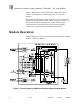
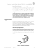
Monitored Guarded Output Modules (T3481/81A, 84 and 88/88A) The processor modules send triplicated write data commands over the I/O Safetybus to the monitored Guarded output module. Onboard the output module the triplicated data are routed to two independent voters which provide voted data to associated field programmable gate arrays (FPGA). Each FPGA independently operates one of the two output control switches. The two output switches are connected in series with the load.
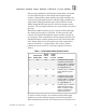
Monitored Guarded Output Modules (T3481/81A, 84, and 88/88A) when one output switch fails off (cases two and four in Table 1). The module failure is automatically detected and the module can be removed and replaced without interrupting output control. Testing and Diagnostics Automatic testing is performed on the monitored guarded output modules as well as the field load connections.
Monitored Guarded Output Modules (T3481/81A, 84 and 88/88A) During testing, the output state is changed; outputs that are on are turned off and outputs that are off are turned on. When two monitored guarded output modules are wired in parallel for fault tolerance, the output circuit testing of the dual modules is coordinated. The test coordination is automatically performed by the system when the modules are properly configured for dual mode (see Configuration, starting on page 17).
Monitored Guarded Output Modules (T3481/81A, 84, and 88/88A) monitored by the application program or external operator interface equipment to dispatch maintenance personnel to correct the field connection problem. Note: Field faults such as open load, shorted load, blown fuse and absence of field power, will mask an output switch fault. When load/fuse faults are detected, they should be repaired as soon as possible.
Monitored Guarded Output Modules (T3481/81A, 84 and 88/88A) Note: When the module is installed in the I/O chassis or when logic power (from the I/O power supply modules) is first applied to the module, it will be in the shutdown mode until the first output scan, regardless of the fault mode jumper settings. Also, removing two I/O transceiver modules, two I/O power supply modules, or two power legs will cause the module to be in the shutdown mode.
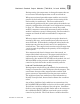
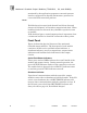
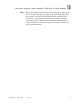
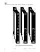
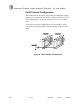
Monitored Guarded Output Modules (T3481/81A, 84, and 88/88A) Figure 2. Monitored Guarded Output Modules.
Monitored Guarded Output Modules (T3481/81A, 84 and 88/88A) Output Status Indicators The output status indicators are yellow LEDs, located on the front of the module. The state of the output circuit is sensed on the field side of the output circuit and optically coupled to both of the FPGAs. The FPGAs logically drive the output status LEDs. The indicator is on when the output circuit is energized. During output testing, the module monitors the current flow to the load device.
Monitored Guarded Output Modules (T3481/81A, 84, and 88/88A) Fault Tolerant Configuration For fault tolerant operation, two monitored Guarded output modules are connected in parallel as shown in Figure 4. In this configuration, operation continues even if one module fails. In the fault tolerant configuration, a failed module can be removed and replaced without interrupting operation of the loads. Figure 4. Fault Tolerant Configuration.
Monitored Guarded Output Modules (T3481/81A, 84 and 88/88A) Fault Tolerant Configuration with Redundant Actuators When redundant actuators are installed in the field, the level of fault protection can be extended to include the field wiring and actuators. Each actuator should be connected to an individual monitored guarded output module as shown in Figure 5. In this configuration continuous operation can be maintained even if a module, field wiring or load fault occurs. Figure 5.
Monitored Guarded Output Modules (T3481/81A, 84, and 88/88A) However, care should be exercised in applying the module to small load devices. Off-state test current (Leakage current ) of the output circuit may prevent some load devices from turning off completely. Table 2 lists the off-state voltages (worst case) for various load ratings and module configurations. These should be compared to the “guaranteed off” voltage for the load device being applied. Table 2. Off-State Voltage Ratings.
Monitored Guarded Output Modules (T3481/81A, 84 and 88/88A) Note: Output circuit testing monitors current flow to the outputs. If the field power supply is not connected, then all of the outputs in the associated group without power will indicate a load/fuse fault condition.
Monitored Guarded Output Modules (T3481/81A, 84, and 88/88A) Figure 6. Fail-Safe Field Wiring.
Monitored Guarded Output Modules (T3481/81A, 84 and 88/88A) Figure 7. Fault Tolerant Field Wiring.
Monitored Guarded Output Modules (T3481/81A, 84, and 88/88A) Fault Mode Jumper The fault mode jumper is located behind the ID switch cover in the lower left-hand corner of each I/O chassis. The position of the fault mode jumper determines the module's response to system level faults. The fault mode jumper’s position will cause all output modules in the I/O chassis to either shutdown (turn off all outputs) or to hold (hold the last state) after a system level failure occurs.
Monitored Guarded Output Modules (T3481/81A, 84 and 88/88A) Figure 8. Installing Slot Keys. Configuration Each output module is configured using the WINTERPRET I/O Configuration Editor. In the editor you will perform the four steps described below to configure the output module.
Monitored Guarded Output Modules (T3481/81A, 84, and 88/88A) 1) Set the Module Type: Position the cursor on the module slot you wish to define. Choose Set Module Type from the Edit Menu and select the appropriate monitored guarded output module from the list. 2) Edit the Module Definition: Choose Edit Module Definition from the Edit Menu. A dialog box will open where you can define the output point definitions. Figure 9. Monitored Guarded Output Module Definition.
Monitored Guarded Output Modules (T3481/81A, 84 and 88/88A) Figure 10. Defining the Guarded Output Module Definition. Note: If you do not configure the modules for Dual Mode then the output testing performed on the modules will not be coordinated and each of the modules wired in parallel will report a fault. Note: For the T3484, 110 VAC Monitored Guarded Output Module you must also select the line frequency of the field power supply. In the Line Frequency drop-down list, select either 50 Hz or 60 Hz.
Monitored Guarded Output Modules (T3481/81A, 84, and 88/88A) Figure 11. Defining a Guarded Digital Output Point. Name Also called the tag name, this is the name used in the application program to reference the output point. The name can be up to 12 characters long. Description This 40-character field provides a place to describe the output point definition. The description is used to help document your system (it does not affect application program operation).
Monitored Guarded Output Modules (T3481/81A, 84 and 88/88A) zero, so that the output is turned off when you delete the application program that controls it. Fault Name This is the name used in the application program to reference the output point line fault status. The name can be up to 12 characters long. During operations the output module is regularly tested for open load, shorted load and blown fuse conditions. If any of these conditions occur, the Fault Name variable will turn on.
Monitored Guarded Output Modules (T3481/81A, 84, and 88/88A) Name represents the 16 output fault names. In each module variable, output 1 is the least significant bit (LSB) and output point 16 is the most significant bit (MSB). The module definition names are not normally used for control purposes. However, they do provide convenient single name references to all 16 outputs points when reporting status information to operator interface equipment.
Monitored Guarded Output Modules (T3481/81A, 84 and 88/88A) Safety Considerations The Monitored Guarded output modules are TÜV certified to Risk Class 5 for safety critical outputs. The modules are approved for de-energize to trip safety critical outputs in single or dual module configurations.
Monitored Guarded Output Modules (T3481/81A, 84, and 88/88A) One 3 amp, 250 V, fast acting (3AB), rectifier type, per output One 2 amp, 250 V, fast acting (3AB), rectifier type, per output One 2 amp, 250 V, fast acting (3AB), rectifier type, per output Littelfuse 322-003 Littelfuse 322-002 Littelfuse 322-002 Turn-On Delay Turn-Off Delay Output Test Duration 0.5 msec 0.5 msec 0.5 msec 0.5 msec 0.5 msec 0.
Monitored Guarded Output Modules (T3481/81A, 84 and 88/88A) Electromagnetic Interference • • • • • IEC 801 Part 2 - Electrostatic Discharges IEC 801 Part 3 - Radiated Electromagnetic Fields IEC 801 Part 4 - Transients and Bursts IEC 801 Part 5 - Surge Immunity ANSI/IEEE C37.90 - Surge Withstand Capability Safety Level 3: Contact discharge of 6 kV Level 3: 10 V/M, 27 MHz 500 MHz Level 4: 2 kV, 2.5 kHz for t=60 sec Level 3: 2 kV 2.
Monitored Guarded Output Modules (T3481/81A, 26 (Issue 2) Industrial 84, and 88/88A) Control Services