ICS Regent ® PD-6026 Guarded Analog Output Modules 4 to 20 mA (T3480) Issue 1, March, 06 Guarded analog output modules provide 4 to 20 mA current outputs for a maximum of six user loads per module. These modules are called Guarded because the module's dualredundant design ensures that no single fault within a module will inadvertently change an output's signal. The module's triplicated Safetybus interface ensures that no Regent system failure will inadvertently affect the output signal.
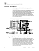
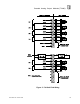
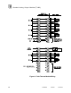
Guarded Analog Output Modules (T3480) Module Operation A block diagram of the Guarded analog output module is shown in Figure 1. The processor modules send triplicated write data commands over the I/O Safetybus to the Guarded output module. Onboard the Guarded output module the triplicated data are routed to two independent voter and I/O Safetybus logic sections. Each section independently votes the triplicated data and drives one digital-to-analog (D/A) converter for each of the six output channels.
Guarded Analog Output Modules (T3480) The combination of redundant interface circuits, D/A converters, and comparison of drive and reference signals produces a fail-safe signal to the load. For fault tolerant operation, two Guarded analog output modules can be used in parallel. In this configuration, the STATUS OUT and STATUS IN signals are cross-strapped between the two redundant modules.
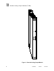
Guarded Analog Output Modules (T3480) shunting all six output channel signal outputs to AGND via the diode matrix. Important! An open circuit wiring fault to a load will cause the output signal comparison for that channel to fail. In single module configurations this may produce undesirable effects. Refer to page 11, Effects of Open Circuit Field Wiring, for further details and recommendations. Front Panel Indicators Figure 2 shows the physical features of a Guarded analog output module.
Guarded Analog Output Modules (T3480) unit is set to shutdown, the red SHUTDOWN indicator will turn on when the communications with the controller are lost. If the I/O unit is set to hold, the SHUTDOWN indicator will always be off (see page 11, Fault Mode Jumper).
Guarded Analog Output Modules (T3480) Figure 2. Guarded Analog Output Module.
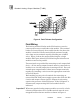
Guarded Analog Output Modules (T3480) Application Guarded analog output modules are suited for high integrity control of analog output devices. Guarded output modules can be used for fail-safe or fault tolerant operation. Fail-Safe Configuration As shown in Figure 3, fail-safe configuration uses a single Guarded module. In this configuration, the worst case failure will cause the output to fail to the off state.
Guarded Analog Output Modules (T3480) Figure 4. Fault Tolerant Configuration. Field Wiring Field wiring terminal blocks on the I/O chassis are used to connect power sources and loads to the module. The terminal blocks are located directly above and below the slot where the module is installed. Each terminal block consists of ten #6 wire clamp screw terminals capable of holding two 12 AWG wires.
Guarded Analog Output Modules (T3480) Figure 5. Fail Safe Field Wiring.
Guarded Analog Output Modules (T3480) Figure 6. Fault Tolerant Module Wiring.
Guarded Analog Output Modules (T3480) Effects of Open Circuit Field Wiring When a Guarded analog output module is controlling the outputs (as opposed to the standby mode) an open circuit in the field wiring connected to a load device will be detected as a failure. This causes the controlling module to switch off, annunciate a fault and enter the standby mode.
Guarded Analog Output Modules (T3480) While in this mode the remaining output loads that have healthy field wiring connections should continue to be controlled correctly because one of the two modules is always in the control mode. Fault Mode Jumper The fault mode jumper is located behind the ID switch cover in the lower left-hand corner of each I/O chassis. The position of the fault mode jumper determines the module's response to system level faults.
Guarded Analog Output Modules (T3480) Figure 7. Installing Slot Keys. Configuration Each output module is configured using the WINTERPRET I/O Configuration Editor. In the editor you will perform the three steps described below to configure the output module.
Guarded Analog Output Modules (T3480) 1) Set the Module Type: Position the cursor on the module slot you wish to define. Choose Set Module Type from the Edit Menu and select the Guarded analog output module from the list. 2) Edit the Module Definition: Choose Edit Module Definition from the Edit Menu. A dialog box will open where you can define the analog output point definitions. Figure 8. Guarded Analog Output Module Definition.
Guarded Analog Output Modules (T3480) Figure 9. Defining an Analog Output Point. Name Also called the tag name, this is the name used in the application program to reference the output point. The name can be up to 12 characters long. Description This 40-character field provides a place to describe the output point definition. The description is used to help document your system (it does not affect application program operation).
Guarded Analog Output Modules (T3480) Programming Outputs are controlled by writing application programs that solve for output values. For example, placing an output tag name in the result field of a math element in ladder logic will set the analog output to the value calculated by the math element. Note that the data range for analog outputs is 0 to 4095 corresponding to the output current rage of 4 to 20 mA.
Guarded Analog Output Modules (T3480) control logic, you maintain the full resolution of the analog output (1 part in 4096) and have a convenient engineering range that represents 0.00 to 100.00% (the two decimal places are implied).
Guarded Analog Output Modules (T3480) · Potentiometer adjustment tool. · Phillips screwdriver · I/O module extender, catalog number T3322. · PC running the WINTERPRET software, used to force the analog output channels to the specific values for calibration. Calibration Preparation The module must be calibrated while connected to an I/O chassis of an operational Regent system.
Guarded Analog Output Modules (T3480) Figure 12. Guarded Analog Output Module Calibration Potentiometer Locations. The I/O extender module has jumper posts that allow you to connect or disconnect the I/O slot field wiring on the I/O chassis to the printed circuit board plugged into the I/O extender. During the calibration steps you will remove any jumpers installed on these posts in order to connect the precision load resistors to the analog outputs.
Guarded Analog Output Modules (T3480) Figure 13. I/O Extender Connections for Guarded Analog Output Calibration. Important! Within each pair of jumper posts, make sure that you connect the resistors to the jumper posts nearest the front of the I/O extender. Do not make any connections to the jumper posts nearest the I/O chassis backplane — these connect to the actual field wiring attached to the I/O slot terminals on the I.O chassis. Calibration Steps 1.
Guarded Analog Output Modules (T3480) 4. Connect the six precision resistors to the I/O extender jumper posts as shown in Figure 13. Use test clips as required to make the connections. 5. Remove the four screws on one side of the module and remove the printed circuit board from the module clamshell housing. 6. Install the printed circuit board into the I/O extender module. Allow the board to warm up for approximately one minute. 7. Connect the voltmeter's negative probe to test point TP4.
Guarded Analog Output Modules (T3480) these steps as there may be some interaction between the gain and offset adjustments. 14. As a final check, use WINTERPRET to force all six outputs to 2048. Wait one minute and verify that the voltage measured across each of the precision resistors is +3.0000 VDC (±0.0002 VDC).
Guarded Analog Output Modules (T3480) the module must be connected (using the I/O extender) to an I/O chassis of an operational Regent system. It is recommended that these tests are performed each time that you calibrate the Guarded analog output module. There are two diodes for each analog output channel that must be tested for latent faults. In addition the fault summary logic is exercised by injecting a fault.
Guarded Analog Output Modules (T3480) Figure 14. Location of Test Points for Latent Fault Testing. Testing Steps 1. Remove the module to be tested from the I/O chassis. 2. Install the I/O extender module into the slot from which the module was removed. 3. Remove the jumpers (if installed) labeled CH1 through CH16 from the I/O extender module.
Guarded Analog Output Modules (T3480) 4. Connect the six termination resistors to the I/O extender jumper posts as shown in Figure 13. Use test clips as required to make the connections. 5. Remove the four screws on one side of the module and remove the printed circuit board from the module clamshell housing. 6. With the printed circuit board removed from the system, check the forward voltage drop (in-circuit) on all 12 output diodes with a digital multimeter in the diode test mode (2 mA current source).
Guarded Analog Output Modules (T3480) fault (green Activity LED turns off and the red Fault LED turns on). 11. Disconnect the one end of the 47K Ohm resistor from TP4. The other end should still be connected to the top lead of the 10K Ohm resistor on RN101. Restore the module to the Active state by performing a voted reset. Now take the end of the 47K Ohm resistor that you removed from TP4 and reconnect it to TP3 (+2VREF). Verify that the module indicates a fault. 12.
Guarded Analog Output Modules (T3480) safety of the process should not be dependent on the operations of the guarded analog output module. To maintain the highest level of integrity, users are advised to periodically perform the calibration and latent fault testing described in the Maintenance section of this document. Refer to page 17 for specific details on performing these procedures. Specifications Safetybus Power 0.8 load units Number of Outputs Six External Power Voltage: Current: 24 VDC ±10% 0.
Guarded Analog Output Modules (T3480) Electromagnetic Interference • • IEC 801 Part 2 - Electrostatic Discharges IEC 801 Part 3 - Radiated Electromagnetic Fields Safety Level 3: Contact discharge of 6 kV Level 3: 10 V/M, 27 MHz 500 MHz Certified to DIN V VDE 0801 (non-interfering) and designed to meet UL 508 and CSA 22.2, No. 142-M1981 Dimensions Height: Width: Depth: Weight 28 12.6" (320 mm) 1.27" (32 mm) 10.12" (257 mm) 3.5 lbs (1.