
Owner's manual

Analog Output Modules
(T3470A)
PD
-
6025
Mar
-
06
15
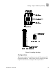
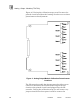
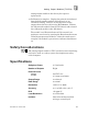
precision load resistors to the analog outputs. Figure
10
shows the jumper posts to which you should connect the
precision resistors for each analog output channel.
Figure
10
. I/O Extender Connections for Analog Output Calibration.
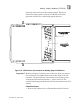
Within each pair of jumper posts, make sure that you connect
the resistors to the jumper posts nearest the front of the I/O
extender. Do not make any connections to the jumper posts
nearest the I/O chassis backplane —
these connect to the
actual field wiring attached to the I/O slot terminals on the I/O
chassis.
Calibration Steps
1.
Remove the module to be calibrated from the I/O chassis.
Important!