
Owner's manual

Analog Output Modules
(T3470A)
14
Industrial Control Services
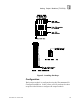
Figure
9
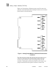
). During the calibration steps you will remove the
printed circuit board from the housing in order to access these
potentiometers for adjustment.
Figure
9
. Analog Output Module Calibration Potentiometer
Locations.
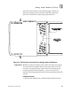
The I/O extender module has jumper posts that allow you to
connect or disconnect the I/O slot field wiring on the I/O
chassis to the printed circuit board plugged into the I/O
extender. During the calibration steps you will remove any
jumpers installed on these posts in order to connect the