ICS Regent ® PD-6021 AC Guarded Digital Output Module 110 VAC (T3464) Issue 1, March, 06 AC Guarded digital output modules provide guarded switching of user-supplied 110 AC voltages to a maximum of sixteen field loads. These modules are called Guarded because no single fault within a module will inadvertently apply power to an output. Extensive fault detection and critical redundant circuits ensure that the module operates in a fail-safe manner.
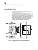
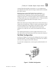
AC Guarded Digital Output Module (T3464) replaced while the other Guarded module continues to control the loads without interruption. Module Operation A block diagram of a typical AC Guarded digital output module is shown in Figure 1. The processor modules send triplicated write data commands over the I/O Safetybus to the Guarded output module. Onboard the Guarded output modules the triplicated data are routed to two independent voter and microcomputer sections.
(T3464) AC Guarded Digital Output Module the TRIAC will be de-energized. If the TRIAC itself fails shorted when commanded off, either microcomputer section can trigger an internal crowbar switch that disables the output by blowing the fuse for that circuit. The combination of dual independent drive signals, a TRIAC, and a crowbar circuit provides fail-safe activation of the load devices. No single failure can prevent the output from being turned off when commanded.
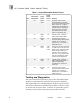
AC Guarded Digital Output Module (T3464) Table 1. Output States After Switch Failure. Actual Output to Load Case Commanded Output State Single Failure 1 On TRIAC short On Continued correct control. Automatic testing of crowbar circuit ensures that output will be able to switch off. If output is subsequently commanded off, crowbar switch is energized to blow fuse and turn off output (fuse blows 200 msec after output is commanded off). 2 On TRIAC open Off Fail-safe output.
(T3464) AC Guarded Digital Output Module module error indication at the processor modules and a module fault indication at the I/O module. Each type of module has a unique identification code that is read by the controller. This code lets the controller know which type of module is installed in each I/O chassis slot and how to address that module and its points specifically. If a module is removed, or is replaced with a module of a different type, the processor modules will indicate an I/O module error.
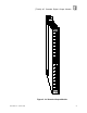
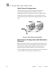
AC Guarded Digital Output Module (T3464) the output switch's ability to conduct current (through an internal dummy load). If current is conducted, the fault is in the load. If no current is conducted, the fault is in the output switch circuit. Healthy outputs commanded to be on but not wired to an external load will always cause an open load condition to be displayed. Front Panel Figure 2 shows the physical features of the AC Guarded output modules.
(T3464) AC Guarded Digital Output Module Figure 2. AC Guarded Output Module.
AC Guarded Digital Output Module (T3464) Diagnostic Message Display This four-digit display provides additional fault diagnostics (such as blown fuse, AC power problems, wiring faults, etc.). If one or more fault conditions are present, the fault messages are displayed in rotation for approximately one second each. These fault messages are self-clearing (which means, for example, that replacing a blown fuse will clear the blown fuse message).
(T3464) AC Guarded Digital Output Module current flows through the neutral wire, so it is important to size both the line and neutral wiring to enable them to handle this fault current. Modules report a open load fault when an output is commanded on and no user load is connected. All output circuits in service must have load connections for proper diagnostic operation. Unused outputs can be left unconnected so long as they are never commanded to be on.
AC Guarded Digital Output Module (T3464) Fault Tolerant Configuration For fault tolerant operation, two Guarded modules are connected in parallel as shown in Figure 4. In this configuration, operation continues even if one module fails. In the fault tolerant configuration, a failed module can be removed and replaced without interrupting operation of the loads. Figure 4. Fault Tolerant Configuration.
(T3464) AC Guarded Digital Output Module Figure 5. Fault Tolerant Configuration with Redundant Actuators. Field Wiring Field wiring terminal blocks on the I/O chassis are used to connect power sources and loads to the module. The terminal blocks are located directly above and below the slot where the module is installed. Each terminal block consists of ten #6 wire clamp screw terminals capable of holding two 12-AWG wires.
AC Guarded Digital Output Module (T3464) Figure 6. Fail-Safe Field Wiring.
(T3464) AC Guarded Digital Output Module Figure 7. Fault Tolerant Field Wiring.
AC Guarded Digital Output Module (T3464) Fault Mode Jumper The fault mode jumper is located behind the ID switch cover in the lower left-hand corner of each I/O chassis. The position of the fault mode jumper determines the module's response to system level faults. The fault mode jumper’s position will cause all output modules in the I/O chassis to either shutdown (turn off all outputs) or to hold (hold the last state) after a system level failure occurs.
(T3464) AC Guarded Digital Output Module Figure 8. Installing Slot Keys. Configuration Each output module is configured using the WINTERPRET I/O Configuration Editor. In the editor you will perform the three steps described below to configure the output module.
AC Guarded Digital Output Module (T3464) 1) Set the Module Type: Position the cursor on the module slot you wish to define. Choose Set Module Type from the Edit Menu and select the relay output module from the list. 2) Edit the Module Definition: Choose Edit Module Definition from the Edit Menu. A dialog box will open where you can define the output point definitions. Figure 9. AC Guarded Output Module Definition.
(T3464) AC Guarded Digital Output Module Name Also called the tag name, this is the name used in the application program to reference the output point. The name can be up to 12 characters long. Description This 40-character field provides a place to describe the output point definition. The description is used to help document your system (it does not affect application program operation).
AC Guarded Digital Output Module (T3464) To program fault tolerant outputs two output coils driven by the same control logic are used as shown in Figure 11. Figure 11. Programming Fault Tolerant Outputs. In this illustration A, B, C, D represent various logic elements used to drive the outputs; XV103A represents the output on one Guarded output module; and XV103B represents the output on the other Guarded output module. Maintenance No periodic maintenance or calibration is required for this module.
(T3464) AC Guarded Digital Output Module Table 3. Initialization Sequence. Step Display Description 1 8.8.8.8. 2 AFO RAM test. Displayed for 1 second. If this test fails, the testing stops and the AFO message remains on. 3 PF PROM test. Displayed briefly. If this test fails, the testing stops and the PF message remains on. 4 ..... Normal display mode. Decimal points blink to indicate processor activity. 5 --.
AC Guarded Digital Output Module (T3464) Table 4. Operating Diagnostic Messages. Display AC Description AC quality problem (i.e. frequency is out of tolerance, frequency is unstable, or phase difference between output groups 1-8 and 9-16). AC.ab AC power failure at field terminals A/B (output group 1-8). AC.cd AC power failure at field terminals C/D (output group 9-16). Shud Outputs are shut down (off). Caused by the loss of controller communications or the module is not configured in the system.
(T3464) AC Guarded Digital Output Module Load Current (maximum) 1 amp maximum per output 0° to 40° C, derated linearly to 0.5 amp at 60° C 16 amps maximum per module at 0° C, derated linearly to 8 amps at 60° C Load Current (minimum) Guarded mode: Fault tolerant mode: 50 mA 150 mA Line Current Load current plus 16 amps transient during crowbar actuation Neutral Current 16 amps maximum transient during crowbar actuation On State Drop 1.
AC Guarded Digital Output Module (T3464) Isolation 2500 volts minimum (field wiring to control logic) 2500 volts minimum (output group 1-8 to output group 9-16) Operating Temperature 0° to 60° C (32° to 140° F) Storage Temperature -40° to 85° C (-40° to 185° F) Operating Humidity 0 to 95% relative humidity, non-condensing Vibration 10 to 55 Hz: ±0.