
Owner's manual

RTD Input Equipment
(T3432)
PD
-
6037
Mar
-
06
23
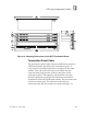
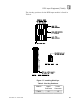
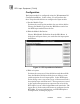
Figure
19
. Defining a RTD Input Point.
Programming
Inputs are referenced in the application program through the
tag na
mes defined in the I/O Configuration Editor. The RTD
inputs variables will be in the engineering units (degrees F or
C) and resolution (1 or 0.1 degree) as configured on the RTD
multiplexer. Because the input data is already represented in
engineering units, there is no need to scale the RTD input
variables in the application program.
The MSB of each RTD input represents out
-
of
-
range (or
NOSIG) status. This bit is normally equal to one. When RTD
inputs are used in application program instruction
s, this MSB
is masked and the sign bit is shifted to the MSB. This allows
the application program instructions to evaluate only the data
portion of the temperature value. This is true for all
application program instructions except Block Move (in ladder
logic). The Block Move instruction moves the entire word of
data without masking off the NOSIG bit.
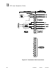
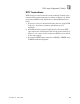
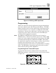
Programming Fault Tolerant RTD Inputs
To program fault tolerant configurations using triplicated
RTD input modules, a midvalue element can be used as sho
wn
in Figure
20
.
Figure
20
. Programming Fault Tolerant RTD Inputs.
Note: