ICS Regent ® PD-6037 RTD Input Equipment Input Module, Mux, Termination Panel and Cable (T3432-IM, T3432-Mux, T3432-TP and T3432-CA) Issue 1, March, 06 The RTD input equipment includes a RTD input module (T3432-IM), a RTD input multiplexer (T3432-MUX), a RTD termination panel (T3432-TP), and a RTD termination cable (T3432-CA). This equipment provides terminations and temperature conversion for as many as 16 RTD inputs, arranged in 2 groups of eight inputs.
RTD Input Equipment (T3432) analog-to-digital conversion. The termination panel can be located as far as 50 cable feet from the I/O chassis. Each module’s triplicated I/O Safetybus interface ensures that no failure in the module can affect the operation of the Regent system or other I/O modules in the system. Extensive fault detection and annunciation of critical redundant circuits help prevent the controllers from receiving erroneous data from a faulty input module.
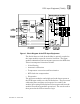
RTD Input Equipment (T3432) Figure 1. Block Diagram of the RTD Input Equipment. The Serial data received from the Mux is optically coupled at the input module to provide electrical isolation. The input module's 68000-based microcomputer processes the RTD data.
RTD Input Equipment (T3432) After receiving the voted data read request, the microcomputer transmits the conditioned temperature data to the Safetybus interface. This interface places the voted temperature data onto the triplicated Safetybus bus drivers. Each of the three bus drivers is independently powered and controlled (by the I/O transceiver modules) — preventing failures in a single driver from propagating to the other two I/O busses.
RTD Input Equipment (T3432) how to address that module and its points specifically. If a module is removed, or is replaced with a module of a different type, the processor modules will indicate an I/O module error. Loopback logic tests periodically write data to the module and then read it back to determine whether the module’s I/O bus interface logic is functioning correctly. Multiplexer Testing The serial communications link to the RTD Mux is continuously monitored.
RTD Input Equipment (T3432) Figure 3. RTD Input Module.
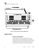
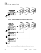
RTD Input Equipment (T3432) Termination Panel and Multiplexer Figure 4 shows the physical features of the RTD termination panel and multiplexer. The multiplexer plugs into the termination panel and is secured in place with two thumb screws located at each end of the multiplexer. Up to three multiplexers can be installed in a single termination panel. Each multiplexer interfaces to a separate RTD input module installed in an I/O Chassis.
RTD Input Equipment (T3432) Figure 4. RTD Termination Panel and Multiplexer. Application Simplex Configuration A single RTD input module and multiplexer provide a suitable interface to non-critical input signals. Although many of the circuits in the RTD input module and multiplexer are automatically tested and annunciated, some logic circuits and field-side sensing circuits are simplex and non-tested. This simplex input configuration is illustrated in Figure 5.
RTD Input Equipment (T3432) Figure 5. Simplex RTD Input Configuration. Fault Tolerant Configurations For safety-critical inputs, redundant input modules and multiplexers are used in a 2oo3 or 1oo2 fault tolerant configuration. In these configurations the redundant RTD input equipment is connected to single or multiple RTDs.
RTD Input Equipment (T3432) Figure 6. Fault Tolerant RTD Input Configuration, Single Sensor. Figure 7. Fault Tolerant RTD Input Configuration, Redundant Sensors.
RTD Input Equipment (T3432) RTD Multiplexer Configuration The RTD input multiplexer provides jumpers to configure the RTD types, noise filtering, temperature units, and temperature resolution. All RTD configuration jumpers are located on the component side of the Mux as shown in Figure 8. The Mux must be removed from the termination panel and the Mux housing disassembled to access the RTD configuration jumpers.
RTD Input Equipment (T3432) Figure 9. Selecting American or European Type RTDs. Selecting 2, 3 or 4-wire RTD Input Lead Configuration. To select the lead configuration for the RTDs, position the jumper for each group as illustrated in Figure 10. The jumper posts are labeled “JP7” for group 1 inputs and “JP8” for group 2 inputs. Note: 2-wire lead configuration is configured the same as 4-wire lead configuration. Figure 10. Selecting 2, 3, or 4-Wire Lead Configuration.
RTD Input Equipment (T3432) posts as illustrated in Figure 11 to configure the type of current sources installed on the termination panel. Figure 11. Selecting 1mA or 5mA Current Source. Noise Filtering RTDs and their associated wiring may be installed in electrically noisy environments. Noise filtering is required to ensure that this noise does not affect the reading of the low level RTD signals. Jumper posts are located on the Mux to select between 50 Hz or 60 Hz noise filtering.
RTD Input Equipment (T3432) Position the jumper on the posts as illustrated in Figure 13 for the desired temperature units. The temperature data resolution must also be configured for units (data increments of 1 degree), or tenths (data increments of 0.1 degree). Position the jumper on the posts as illustrated in Figure 13 for the desired data resolution. Note: The RTD data is always presented as integer data to the processor modules.
RTD Input Equipment (T3432) Table 1. Temperature Data Ranges. Out-of-Range Detection When the RTD measures temperatures outside of the operating range listed in Table 1, the signal is considered to be out-of-range. The RTD equipment will continue to provide over-range and under-range readings up to the minimum and maximum readings shown in the Table. Also, many open-circuit and short-circuit wiring faults will cause out-of-range conditions for RTD inputs.
RTD Input Equipment (T3432) 1. For unused input channels, short the +SENSE, -SENSE, and -FORCE terminals together. This will eliminate any floating readings for the unused channels. 2. Minimize the resistance of the RTD extension wire by using heavier wire gauges. The RTD input circuit supports a maximum 20 Ohms lead resistance. Radiated Field Susceptibility Transmitting equipment should not be operated within the vicinity of the termination panel.
RTD Input Equipment (T3432) Figure 14. Mounting Dimensions for the RTD Termination Panel. Termination Panel Cable The termination panel cable connects a RTD input module to a RTD multiplexer installed in the termination panel. It carries power to the Mux and routes serial data to the input module. One end of the cable has a male DB-9 nine-pin connector that plugs into one of three connectors on the termination panel.
RTD Input Equipment (T3432) Figure 15. Termination Cable Connections.
RTD Input Equipment (T3432) RTD Terminations RTD wiring is connected to the screw terminals located at the bottom of the termination panel as shown in Figure 16. When terminating RTD wiring, follow the recommendations listed below. 1. Greater accuracy is maintained with a heavier gauge RTD lead wire. Lead wire resistance should not exceed 20 Ohms. 2. All RTDs within a group of eight must be the same RTD type (American or European) and use the same number of leads (2, 3 or 4-wire).
RTD Input Equipment (T3432) Figure 16. Wiring RTDs to Termination Panel. Keying The I/O chassis can be physically keyed to prevent accidental damage caused by inserting a module into a slot wired for a different module type. Figure 17 illustrates how the slot keys are installed on the I/O chassis slot field wiring connectors.
RTD Input Equipment (T3432) The slot key positions for the RTD input module is listed in Table 2. Figure 17. Installing Slot Keys. Table 2. Slot Key Positions.
RTD Input Equipment (T3432) Configuration Each input module is configured using the WINTERPRET I/O Configuration Editor. In the editor, you will perform the three steps described below to configure the input module. 1) Set the Module Type: Position the cursor on the module slot you wish to define. Choose Set Module Type from the Edit Menu and select the RTD input module from the list. 2) Edit the Module Definition: Choose Edit Module Definition from the Edit Menu.
RTD Input Equipment (T3432) Figure 19. Defining a RTD Input Point. Programming Inputs are referenced in the application program through the tag names defined in the I/O Configuration Editor. The RTD inputs variables will be in the engineering units (degrees F or C) and resolution (1 or 0.1 degree) as configured on the RTD multiplexer. Because the input data is already represented in engineering units, there is no need to scale the RTD input variables in the application program.
RTD Input Equipment (T3432) In this illustration, VALUE_A_NAME, VALUE_B_NAME, and VALUE_C_NAME represent the three RTD inputs to be mid-value selected. ERROR_A_NAME, ERROR_B_NAME and ERROR_C_NAME are the error bits for the RTD inputs. RESULT_NAME is the result of the mid-value instruction. The field Limit is the integer value, in similar units to the Value A, B and C variables, that a RTD input can deviate from the mid-value result before signaling an error (via the Error A, B or C bits).
RTD Input Equipment (T3432) points of failure and extend fault tolerance to include the RTDs. For additional safety considerations, please refer to the Safety Considerations section of the Regent User’s Guide. Specifications Safetybus Power 1.8 load units Number of Inputs 16, two, three, or four-wire RTDs RTD Input Types American: European: 100W Platinum a = 0.00392 W/W/° C a = 0.
RTD Input Equipment (T3432) Common Mode Rejection 100 dB @ 50/60 Hz 60 dB minimum, elsewhere Normal Mode Rejection 70 dB typical Termination Panel Cable Length Isolation Maximum 50 cable feet (15 m) 2500 volts minimum (Mux to input module) Operating Temperature 0° to 60° C (32° to 140° F) Storage Temperature -40° to 85° C (-40° to 185° F) Operating Humidity 0 to 95% relative humidity, non-condensing Safety Pending certification to DIN V VDE 0801 for Risk Class 5.