ICS Regent ® PD-6024 Thermocouple Input Assembly Input Module, Mux, Termination Panel and Cable (T3431-IM, T3431-Mux, T3431-TP and T3431-CA) Issue 1, March, 06 The thermocouple input assembly consists of a thermocouple input module (T3431-IM), a thermocouple input multiplexer (T3431-MUX), a thermocouple termination panel (T3431-TP), and a thermocouple termination cable (T3431-CA).
Thermocouple Input Assembly (T3431) multiplexing, and analog-to-digital conversion. The termination panel can be located as far as 50 cable feet from the I/O chassis. Each module’s triplicated I/O Safetybus interface ensures that no failure in the module can affect the operation of the Regent system or other I/O modules in the system. Extensive fault detection and annunciation of critical redundant circuits help prevent the controllers from receiving erroneous data from a faulty input module.
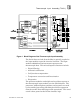
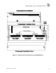
Thermocouple Input Assembly (T3431) Figure 1. Block Diagram of the Thermocouple Input Assembly. The Serial data received from the Mux is optically coupled at the input module to provide electrical isolation. The input module's 68000-based microcomputer processes the thermocouple data.
Thermocouple Input Assembly (T3431) After receiving the voted data read request, the microcomputer transmits the conditioned temperature data to the Safetybus interface. This interface places the voted temperature data onto the triplicated Safetybus bus drivers. Each of the three bus drivers is independently powered and controlled (by the I/O transceiver modules) — preventing failures in a single driver from propagating to the other two I/O busses.
Thermocouple Input Assembly (T3431) Each type of module has a unique identification code that is read by the controller. This code lets the controller know which type of module is installed in each I/O chassis slot and how to address that module and its points specifically. If a module is removed, or is replaced with a module of a different type, the processor modules will indicate an I/O module error.
Thermocouple Input Assembly (T3431) Failure of the DC-to-DC converter supplying power to the termination panel or the receiver circuitry can also result in a MUX fault. Both of these faults are input module faults. CJ Fault Indicator There are two cold junction sensors located on the termination panel.
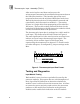
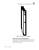
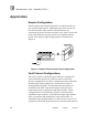
Thermocouple Input Assembly (T3431) Figure 3. Thermocouple Input Module. Termination Panel and Multiplexer Figure 4 shows the physical features of the Termination Panel and Multiplexer. The multiplexer plugs into the termination panel and is secured in place with two thumb screws located at each end of the multiplexer.
Thermocouple Input Assembly (T3431) The termination cable plugs into the DB-9 connector located at the upper right corner of the termination panel. Thermocouple inputs are terminated at the screw terminals located along the bottom of the termination panel. These terminals are arranged in three groups of eight inputs. Two screw terminals are provided for each thermocouple input. Two additional ground terminals within each group are provided to connect thermocouple cable shield wires if desired.
Thermocouple Input Assembly (T3431) Figure 4. Thermocouple Termination Panel and Multiplexer.
Thermocouple Input Assembly (T3431) Application Simplex Configuration Thermocouple input modules provide a suitable interface to non-critical input signals. Although many of the circuits in the thermocouple input module and multiplexer are automatically tested and annunciated, some logic circuits and most of the field-side sensing circuits are simplex and nontested. This simplex input configuration is illustrated in Figure 5. Figure 5. Simplex Thermocouple Input Configuration.
Thermocouple Input Assembly (T3431) while the system continues to sense the inputs from the remaining two sets of equipment. Figure 6. Fault Tolerant Thermocouple Input Configurations.
Thermocouple Input Assembly (T3431) Thermocouple Multiplexer Configuration The thermocouple input multiplexer provides jumpers to configure the thermocouple types, noise filtering, temperature units, and temperature resolution. All thermocouple configuration jumpers are located on the component side of the Mux as shown in Figure 7. To access these jumpers the Mux must be removed from the termination panel. Figure 7. Location of Configuration Jumpers on Mux.
Thermocouple Input Assembly (T3431) Note: There are four unused codes. Using any of these codes will cause a Mux fault indication. Thermocouple Noise Filtering Thermocouples and their associated wiring may be installed in electrically noisy environments. Noise filtering is required to ensure that this noise does not affect the reading of the low level thermocouple signals. Three jumper posts are located on the Mux to select between 50 Hz or 60 Hz digital filtering.
Thermocouple Input Assembly (T3431) T/C Type Scale J K S T Lower Limit Upper Limit Lower Limit Upper Limit Lower Limit Upper Limit ºC 0 750 0 750 0.0 750.0 ºF 32 1382 32 1382 32.0 1382.0 ºC -200 1250 -200 1250 -200.0 1250.0 ºF -328 2282 -328 2282 -328.0 1638.3 ºC 0 1450 0 1450 0.0 1450.0 ºF 32 2642 32 2642 32.0 1638.3 ºC -200 350 -200 350 -200.0 350.0 ºF -328 662 -328 662 -328.0 662.0 Note for thermocouple types K and S: If a 0.
Thermocouple Input Assembly (T3431) block areas. Install the thermocouple terminations cover provided with the termination panel. Allow at least four hours for temperature stabilization after any significant temperature change. 2. If possible, terminate unused input channels with the same thermocouple signal as the next channel, or short the terminals of the unused input. This will minimize the pulling affect of a preceding input. 3.
Thermocouple Input Assembly (T3431) Figure 8. Mounting Dimensions for the Termination Panel. Termination Panel Cable The termination panel cable connects the input module to the termination panel. It carries power to the panel and routes serial data to the input module. One end of the cable has a male DB-9 nine-pin connector that plugs into the termination panel. The opposite end should be cut to the desired length and wired to the I/O chassis terminal block immediately above the input module.
Thermocouple Input Assembly (T3431) Figure 9. Termination Cable Connections.
Thermocouple Input Assembly (T3431) Thermocouple Terminations Thermocouple wires are connected to the screw terminals located at the bottom of the termination panel as shown in Figure 10. When terminating thermocouple wiring, follow the recommendations listed below. 1. Greater accuracy is maintained with a heavier gauge thermocouple extension wire. 2. All thermocouples within a group of eight must be the same thermocouple type. 3.
Thermocouple Input Assembly (T3431) Keying The I/O chassis can be physically keyed to prevent accidental damage caused by inserting a module into a slot wired for a different module type. Figure 11 illustrates how the slot keys are installed on the I/O chassis slot field wiring connectors. The slot key positions for the thermocouple input module is listed in Table 3. Figure 11. Installing Slot Keys.
Thermocouple Input Assembly (T3431) Table 3. Slot Key Positions. Module Upper Connector Lower Connector T3431 15 15 Configuration Each input module is configured using the WINTERPRET I/O Configuration Editor. In the editor, you will perform the three steps described below to configure the input module. 1) Set the Module Type: Position the cursor on the module slot you wish to define. Choose Set Module Type from the Edit Menu and select the thermocouple input module from the list.
Thermocouple Input Assembly (T3431) used in the application program to represent the value of the thermocouple input in your control algorithms and interlocks. The input data is in the units and format as configured on the thermocouple Mux. For more information, see Thermocouple Multiplexer Configuration, starting on page 12. Figure 13. Defining a Thermocouple Input Point. Programming Inputs are referenced in the application program through the tag names defined in the I/O Configuration Editor.
Thermocouple Input Assembly (T3431) Programming Fault Tolerant Thermocouple Inputs To program fault tolerant configurations using triplicated thermocouple input modules, a midvalue element can be used as shown in Figure 14. Figure 14. Programming Fault Tolerant Thermocouple Inputs. In this illustration, VALUE_A_NAME, VALUE_B_NAME, and VALUE_C_NAME represent the three thermocouple inputs to be mid-value selected. ERROR_A_NAME, ERROR_B_NAME and ERROR_C_NAME are the error bits for the T/C inputs.
Thermocouple Input Assembly (T3431) Maintenance Calibration The Mux contains an ultra-stable voltage reference circuit for auto-calibration of all thermocouple channels. This circuit does not require re-adjustment. Cold junction sensors do not require re-adjustment. Troubleshooting The following procedure is used for troubleshooting the thermocouple input. The only assumption made is that the input module fault indicator is on. 1. If both the Mux and CJ indicators are off, replace the input module. 2.
Thermocouple Input Assembly (T3431) Safety Considerations The thermocouple input modules are TÜV certified as noninterfering and can be used for non-safety critical inputs in Risk Class 5 safety applications. For additional safety considerations, please refer to the Safety Considerations section of the Regent User’s Guide. Specifications Safetybus Power 1.
Thermocouple Input Assembly (T3431) Input to Chassis Resistance 1.
Thermocouple Input Assembly (T3431) Thermocouple Accuracy Maximum error (0° to 60° C). Add ±0.5 LSB resolution error to the following: Type J, Full range: Type K < -100° C: > -100° C: Type S < 540° C: > 540° C: Type T < 0° C: > 0° C: ±1.6° C (3.0° F) ±4.2° C (7.6° F) ±2.4° C (4.3° F) ±13° C (24° F) ±7° C (12.5° F) ±4.8° C (8.7° F) ±2.1° C (3.8° F) Wire Resistance Effects Type J, Full range: Type K < -100° C: > -100° C: Type S < 540° C: > 540° C: Type T < 0° C: > 0° C: -0.0020° C/ohm (.0036° F) -0.
Thermocouple Input Assembly (T3431) Termination Panel Cable Length Isolation Maximum 50 cable feet (15 m) 2500 volts minimum (field wiring to control logic) Operating Temperature 0° to 60° C (32° to 140° F) Storage Temperature -40° to 85° C (-40° to 185° F) Operating Humidity 0 to 95% relative humidity, non-condensing Safety Certified to DIN V VDE 0801 (non-interfering) and designed to meet UL 508 and CSA 22.2, No. 142-M1981 Heat Dissipation Input module: Termination panel/Mux: 4.