
Manual

Fire Detector Input Modules
(T3419)
PD
-
6032
Mar
-
06
5
If the I/O processors detect a faulted input circuit, an I/O
module fault is indicated at the processor modules and the
Fault LED on the face of the input module is turned on.
Input C
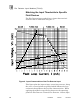
ircuit Test Interval
The Regent processor modules schedule testing of the input
circuits on a background basis. The test interval for these
circuits may range from a few seconds to several minutes,
depending on the application program scan time and the size
of the I/O configuration. The equation below can be used to
estimate the test interval for monitored digital inputs.
TI = 172 * IOU
QTY
* TSCAN + 2
where:
TI
=
Test interval, seconds
IOU
QTY
=
Quantity of I/O Units in the system (1 to 16)
TSCAN
= T
he application program scan time, seconds
For example, for a system with 8 I/O units and an application
scan time of 60 milliseconds, the test interval would be:
TI = 172 * IOU
QTY
* TSCAN + 2 = 172 * 8 * 0.060 + 2
TI = 84.6 seconds
In this system, all of the fire detector input modules would be
tested for stuck
-
on and stuck
-
off faults approximately every 85
seconds. This test interval can be used in reliability and
availability calculations to select the fault tolerant input
configuration that meet the application’s safety requirements.
Due to I/O processor fault filtering algorithms, it may take up
to four test intervals to report a failed input module as a
permanent fault
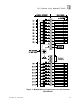
Front Panel Indicators
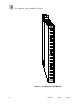
Figure
2
shows the physical features of the fire detector input
modules. The front panel of each module contains fault/active
and power indicators for the module as well as input status
indicators for each channel.
Note: