ICS Regent ® PD-6027 Monitored Digital Input Modules, Field Powered (Type F) 24 to 48 VDC, 120 VAC/DC (T3411F, T3418F) Issue 1, March, 06 Monitored digital input modules provide input sensing for 16 field input devices. The field powered (Type F) modules are suitable for inputs that are directly powered from an external field power supply. Two types of modules are available for inputs powered from 24 to 48 VDC and 120 VAC/DC.
Monitored Digital Input Modules, Type F (T3411F, T3418F) Two or three monitored digital input modules can be connected in parallel to obtain fault tolerant input sensing. In these fault tolerant configurations, a failed module can be removed and replaced without interrupting the input signals. The module requires connection to the same field power supply that powers the field switches. This field power is internally regulated by the module to power the module’s input interface circuits.
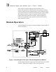
Monitored Digital Input Modules, Type F (T3411F, T3418F) monitored input module. The field power is internally regulated to power the input module’s field interface circuits. The switched side of each input is wired back to the input module terminal screws. Inside the input module the signal passes through an internal dropping resistor and back to the field power supply return. Optionally a line monitor device can be connected across the input switch in the field (as shown in Figure 1).
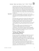
Monitored Digital Input Modules, Type F (T3411F, T3418F) The bus drivers then move the data onto the I/O Safetybus which, in turn, passes it to the processors. Each module’s voter circuits are periodically tested by the processor modules. Discrepant data are sent through one of three legs of the I/O Safetybus to determine whether the module’s voter is able to outvote the incorrect data.
Monitored Digital Input Modules, Type F (T3411F, T3418F) off failure modes. During testing the D/A converter generates two reference voltages outside the normal operating range of the field input voltages to test that the comparator output can turn-off and turn-on. The I/O processors read the resulting input status, line fault status, and reference voltage readings for the test cycle to determine if there are faults in the input circuits or the common data paths.
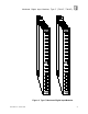
Monitored Digital Input Modules, Type F (T3411F, T3418F) Front Panel Indicators Figure 2 shows the physical features of the type F, monitored digital input modules. The front panel of each module contains fault/active and power indicators for the module as well as input status indicators for each channel. Active/Fault Status Indicator This green and red LED pair indicates the overall health of the module and its field circuits.
Monitored Digital Input Modules, Type F (T3411F, T3418F) Figure 2. Type F, Monitored Digital Input Modules.
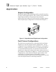
Monitored Digital Input Modules, Type F (T3411F, T3418F) Application Simplex Configuration Monitored digital input modules provide a suitable interface to safety-critical input signals. The circuits in the monitored digital input modules are automatically tested and annunciated, providing a fail-safe interface to digital inputs. This simplex input configuration is illustrated in Figure 3. Figure 3. Single Monitored Digital Input Configuration.
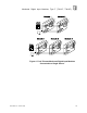
Monitored Digital Input Modules, Type F (T3411F, T3418F) Figure 4. Fault Tolerant Monitored Digital Input Modules Connected to a Single Sensor.
Monitored Digital Input Modules, Type F (T3411F, T3418F) Figure 5. Fault Tolerant Monitored Digital Input Modules Connected to Redundant Sensors. Field Wiring Field wiring terminal blocks on the I/O chassis are used to connect the field power supply and field input wiring to the monitored input module. The terminal blocks are located directly above and below the slot where the module is installed. Each terminal block consists of ten #6 wire clamp screw terminals capable of holding two 12 AWG wires.
Monitored Digital Input Modules, Type F (T3411F, T3418F) The field power supply voltage is regulated inside the module to power the module’s input interface circuits. The power supply is also wired directly to the field input switches and the switched side is wired back to the input module. Inside the input module the input signal passes through a dropping resistor and connects back to the power supply return. Figure 6 shows the wiring connections for a single monitored input module.
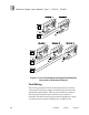
Monitored Digital Input Modules, Type F (T3411F, T3418F) Figure 6. Module Wiring, Single Sensors to a Single Monitored Digital Input Module.
Monitored Digital Input Modules, Type F (T3411F, T3418F) Figure 7. Module Wiring, Single Sensors to Redundant Monitored Digital Input Modules.
Monitored Digital Input Modules, Type F (T3411F, T3418F) Line Monitoring For DC powered inputs, the monitored digital input module can perform line monitoring of the field wiring when a suitable line monitor device is installed across the field input switch. A variety of line monitor devices are available to match the voltage and input redundancy used in the application. Figure 8 shows a single switch connected to a single monitored input module.
Monitored Digital Input Modules, Type F (T3411F, T3418F) Figure 9 shows a single switch connected to a redundant monitored input modules. This type of configuration uses a line monitor device which contains two zener diodes, one in series with the field switch and one in parallel with the field switch. Figure 9. Line Monitoring, Single Switch Connected to Redundant Modules.
Monitored Digital Input Modules, Type F (T3411F, T3418F) With the line monitor device installed, the input voltage, Vin, has four possible states as represented in Table 1. When the input module reads the input, the reference voltage, Vref, is set to the values shown in Table 1 to detect the state of the input. Table 1. Input States and Reference Voltage Thresholds.
Monitored Digital Input Modules, Type F (T3411F, T3418F) Figure 10. Installing Slot Keys. Table 2. Slot Key Positions.
Monitored Digital Input Modules, Type F (T3411F, T3418F) Configuration Each monitored input module is configured using the WINTERPRET I/O Configuration Editor. In the editor, you will perform the steps described below to configure the input module. 1) Set the Module Type: Position the cursor on the module slot you wish to define. Choose Set Module Type from the Edit Menu and select either the T3411F or T3418F monitored digital input module from the list.
Monitored Digital Input Modules, Type F (T3411F, T3418F) Figure 12. Defining the Input Module Fields and Thresholds. In the module definition dialog you can define a tag names representing all sixteen input points as a 16-bit word. The Name field represents the On/Off status of all sixteen inputs and the Fault Name represents the Line Fault status of all sixteen inputs. The module tag names represents the 16 inputs as a signed, 16-bit integer.
Monitored Digital Input Modules, Type F (T3411F, T3418F) Line Monitored Input Point dialog, enter names and values for the configuration fields as described below. Figure 13. Defining a Monitored Digital Input Point. Name Also called the tag name, this is the name used in the application program to reference the field input switch’s On/Off state. The name can be up to 12 characters long. Description This 40-character field provides a place to describe the input point definition.
Monitored Digital Input Modules, Type F (T3411F, T3418F) Note: Line fault status is only reported through the Fault Name variables. Line faults are not reported as a permanent I/O module fault and do not turn on the associated system control relay fault bit for the module. Line faults are not latched. If a line fault condition returns to normal, the Fault Name variable status also returns to normal.
Monitored Digital Input Modules, Type F (T3411F, T3418F) short or open circuit (or there is no line monitor device installed) the Fault Name status is off. The status of the Name and Fault Name input variables are summarized in Table 3 for the various field input conditions. Table 3. Input Status for Field Input Conditions.
Monitored Digital Input Modules, Type F (T3411F, T3418F) represent the voted value of the two inputs. This variable would be used elsewhere in the application program to represent the status of the field input in the associated safety interlock logic. When both input modules are healthy, both inputs must turn off to turn off the voted result and initiate a trip. Because the inputs are normally energized, the voted result is normally on.
Monitored Digital Input Modules, Type F (T3411F, T3418F) the input module and performing a voted reset, the fault bit is turned off, restoring the input configuration to the dual mode. Programming Triple Fault Tolerant Monitored Inputs Fault tolerant applications that include triplicated monitored input modules should use the Voter instruction in ladder logic. The voter instruction performs two-out-of-three voting of triplicated inputs, storing the voted result in the defined shared variable.
Monitored Digital Input Modules, Type F (T3411F, T3418F) For additional safety considerations, please refer to the Safety Considerations section of the Regent User’s Guide. Specifications Safetybus Power Number of Inputs Field Power Voltage, min.: Voltage, max.: Current: Turn-On Voltage (default) Turn-Off Voltage (default) Input Current Turn-On Delay Turn-Off Delay Over Voltage Protection Field Power Terminals: Input Terminals: Heat Dissipation Fusing Isolation PD-6027 Mar-06 0.
Monitored Digital Input Modules, Type F (T3411F, T3418F) Input Circuit Test Interval Intrinsic Safety Operating Temperature Storage Temperature Operating Humidity Function of application program scan time and size of I/O configuration. Typically less than 2 seconds (see page 5 for details). External barrier, if required. (requires threshold adjustment, see page 18). 0° to 60° C (32° to 140° F) -40° to 85° C (-40° to 185° F) 0 to 95% relative humidity, non-condensing Vibration 10 to 55 Hz: ±0.
Monitored Digital Input Modules, Type F (T3411F, T3418F) Dimensions Height: Width: Depth: Weight PD-6027 Mar-06 12.6" (320 mm) 1.27" (32 mm) 10.12" (257 mm) 3.3 lbs (1.