ICS Regent ® PD-6031 Monitored Digital Input Modules 24 VDC (T3411) Issue 1, March, 06 Monitored digital input modules provide input sensing for 16 field input devices. With a line monitor device installed at the field switch, monitored digital input modules detect input switch status and field wiring open and short circuits. Input and line status are reported back to the controller for use in application program logic. Features · Sixteen input points.
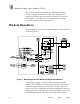
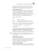
Monitored Digital Input Modules (T3411) The module requires connection to a field power supply voltage, ranging from 15 to 80 VDC. This field power is internally regulated by the module to 24 VDC to power the field inputs — providing safe, low-voltage inputs signals common in safety system applications. Module Operation A block diagram of a typical monitored digital input module is shown in Figure 1. Figure 1. Block Diagram of the Monitored Digital Input Module.
Monitored Digital Input Modules (T3411) wired back to the field power supply return. Optionally a line monitor device can be connected across the input switch in the field (as shown in Figure 1). The input module monitors the voltage of the input circuit after the internal dropping resistor, comparing it to a reference voltage generated by the D/A converter inside the module. The comparator generates an on or off state depending on which voltage signal is greater than the other.
Monitored Digital Input Modules (T3411) Each type of module has a unique identification code that is read by the controller. This code lets the controller know which type of module is installed in each I/O chassis slot and address that module and its points specifically. The processor modules periodically check each module’s identification code to determine whether the type of module installed matches type of module indicated in the I/O configuration that was loaded when the system was started.
Monitored Digital Input Modules (T3411) If the I/O processors detect a faulted input circuit, an I/O module fault is indicated at the processor modules and the Fault LED on the face of the input module is turned on. Input Circuit Test Interval The Regent processor modules schedule testing of the input circuits on a background basis. The test interval for these circuits may range from a few seconds to several minutes, depending on the application program scan time and the size of the I/O configuration.
Monitored Digital Input Modules (T3411) green ACTIVE indicator flashes at the controller's scan rate. If a module fault occurs the red FAULT indicator turns on and the green indicator turns off. Power Status Indicator The POWER GOOD LED indicates the presence of field voltage at the module’s field power input terminals and the overall health of the module’s field power regulator circuits. Input Status Indicators Input status indicators show contact and line status for each point.
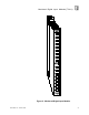
Monitored Digital Input Modules (T3411) Figure 2. Monitored Digital Input Module.
Monitored Digital Input Modules (T3411) Application Simplex Configuration Monitored digital input modules provide a suitable interface to safety-critical input signals. The circuits in the monitored digital input modules are automatically tested and annunciated, providing a fail-safe interface to digital inputs. This simplex input configuration is illustrated in Figure 3. Figure 3. Single Monitored Digital Input Configuration.
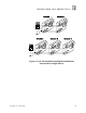
Monitored Digital Input Modules (T3411) Figure 4. Fault Tolerant Monitored Digital Input Modules Connected to a Single Sensor.
Monitored Digital Input Modules (T3411) Figure 5. Fault Tolerant Monitored Digital Input Modules Connected to Redundant Sensors. Field Wiring Field wiring terminal blocks on the I/O chassis are used to connect the field power supply and field input wiring to the monitored input module. The terminal blocks are located directly above and below the slot where the module is installed. Each terminal block consists of ten #6 wire clamp screw terminals capable of holding two 12 AWG wires.
Monitored Digital Input Modules (T3411) The field power supply voltage is regulated to 24 Vdc inside the module. This power is used to source the power to the field input switches. The return side of the field switches is wired back to the field power supply return. Figure 6 shows the wiring connections for a single monitored input module. When redundant field sensors are installed, each input module is wired as shown in Figure 6.
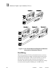
Monitored Digital Input Modules (T3411) Figure 6. Module Wiring, Single Sensors to a Single Monitored Digital Input Module.
Monitored Digital Input Modules (T3411) Figure 7. Module Wiring, Single Sensors to Redundant Monitored Digital Input Modules.
Monitored Digital Input Modules (T3411) Line Monitoring The Monitored digital input module can perform line monitoring of the field wiring when a suitable line monitor device is installed across the field input switch. Two types of line monitor devices are available to match the type of module configuration used in the application. Figure 8 shows a single switch connected to a single monitored input module.
Monitored Digital Input Modules (T3411) Figure 9. Line Monitoring, Single Switch Connected to Redundant Modules. With the line monitor device installed, the input voltage, Vin, has four possible states as represented in Table 1. When the input module reads the input, the reference voltage, Vref, is set to the values shown in Table 1 to detect the state of the field input and wiring. Table 1. Input States and Reference Voltage Thresholds.
Monitored Digital Input Modules (T3411) Keying The I/O chassis can be physically keyed to prevent accidental damage caused by inserting a module into a slot wired for a different module type. Figure 10 illustrates how the slot keys are installed on the I/O chassis slot field wiring connectors. The slot key positions for the monitored digital input module are listed in Table 2. Figure 10. Installing Slot Keys.
Monitored Digital Input Modules (T3411) Table 2. Slot Key Positions. Module Upper Connector Lower Connector T3411 4 7 Configuration Each monitored input module is configured using the WINTERPRET I/O Configuration Editor. In the editor, you will perform the steps described below to configure the input module. 1) Set the Module Type: Position the cursor on the module slot you wish to define.
Monitored Digital Input Modules (T3411) 3) Define the Input Module Fields and Thresholds: With the cursor at the top of the list in the Module Definition dialog shown in Figure 11, open the Line Monitored Input Module dialog by pressing Enter or double clicking on the “(Module)” selection. The dialog box shown in Figure 12 will open. Figure 12. Defining the Input Module Fields and Thresholds. In the module definition dialog you can define a tag names representing all sixteen input points as a 16-bit word.
Monitored Digital Input Modules (T3411) inputs with the standard (T0412 and T0413) line monitor devices installed. If non-standard line monitor devices are installed, then the threshold values may need to be adjusted. 3) Edit each point: Choose Edit from the Module Definition dialog box to define a name and description for each input point. In the Line Monitored Input Point dialog, enter names and values for the configuration fields as described below. Figure 13. Defining a Monitored Digital Input Point.
Monitored Digital Input Modules (T3411) During operations the input circuit is monitored for open circuit and short circuit wiring faults. This bit is normally on and turns off if either an open circuit or short circuit is detected. Note: Line fault status is only reported through the Fault Name variables. Line faults are not reported as a permanent I/O module fault and do not turn on the associated system control relay fault bit for the module. Line faults are not latched.
Monitored Digital Input Modules (T3411) Field wiring open circuit or short circuit conditions are referenced in the application program using the Fault Name tag names defined in the I/O configuration Editor. When a line monitor device is installed across the field switch and the wiring is healthy, the Fault Name status is on. If there is a short or open circuit (or there is no line monitor device installed) the Fault Name status is off.
Monitored Digital Input Modules (T3411) In this example, IN1A and IN1B represent the input variables from two redundant monitored input modules. IO01U01 and IO01U02 are the system control relays that report a fault for the monitored input modules (one installed in slot 1 of chassis 1 and the other in slot 1 of chassis 2). The variable IN1VOTE is a shared control relay that will represent the voted value of the two inputs.
Monitored Digital Input Modules (T3411) result will remain off, eliminating a nuisance trip. Automatic testing of the input module will detect the fault and the associated fault bit will be turned on, allowing the voted result to be controlled by the remaining healthy input module. The faulted module can be removed and replaced. After replacing the input module and performing a voted reset, the fault bit is turned off, restoring the input configuration to the dual mode.
Monitored Digital Input Modules (T3411) If energize-to-trip inputs are used in safety critical applications, line monitor devices must be installed at the field switches. The Fault Name variables must be configured and line fault status must be alarmed to plant operations personnel. For de-energize-to-trip inputs, line monitor devices are recommended in order to detect the difference between a normally closed input and a shorted field wire.
Monitored Digital Input Modules (T3411) Intrinsic Safety Operating Temperature Storage Temperature Operating Humidity External barrier, if required. (requires threshold adjustment, see page 18). 0° to 60° C (32° to 140° F) -40° to 85° C (-40° to 185° F) 0 to 95% relative humidity, non-condensing Vibration 10 to 55 Hz: ±0.
Monitored Digital Input Modules (T3411) 26 Industrial Control Services