
Manual

AC Digital Input Module
(T3404)
12
Industrial Control Services
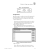
Digital Input Point dialog, enter a tag name (up to 12
characters) and a description (up to 40 cha
racters).
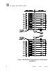
Figure
9
. Defining a Digital Input Point.
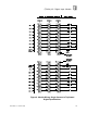
The tag names are used in the application program to
represent the input state. In addition, a module tag name can
be entered to represent the combined state of all 16 inputs.
This module tag name represents the 16 inputs as a signed,
16
-
bit integer. In this format, input point one is the least
significant bit (LSB) and input point 16 is the most significant
bit (MSB).
Programming
Inputs are referenced in the application program through the
tag names defined in the I/O Configuration Editor. When
current flows through the input (field switch closed) the input
is said to be on, or have a value of one. In ladder logic, the on
state would produce power flow in a normally open (N.O.)
contact.
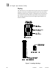
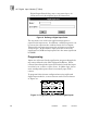
To program fault tolerant configurations using triplicated
digital input modules, a voter element can be used as shown
in Figure
10
.
Figure
10
. Programming Fault Tolerant Digital Inputs.