
User Manual

Real
-
Time Clock Communications Modules
(T3151)
8
Industrial Control Services
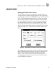
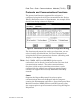
Table
1
. Real
-
Time Clock System Registers.
Unit
Read Clock
Tag Name
Set Clock
Tag Name
Year
RTCYEAR
SETYEAR
Month
RTCMNTH
SETMNTH
Day of Month
RTCDOM
SETDOM
Day of Week
RTCDOW
SETDOW
Hour
RTCHOUR
SETHOUR
Minute
RTCMIN
SETMIN
Second
RTCSEC
SETSEC
Millisecond
RTCMS
(always set to 0)
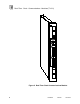
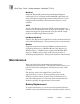
Communication Port Connections
Each communications port has a DB
-
25, female connector on
the front of the module. The RS232 signals are internally
connected to the DB
-
25 connector pins listed in Table
2
.
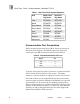
Table
2
. Communications Port Pi
n
-
out.
Signal
Pin
TXD
2
RXD
3
GND
7
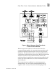
Typically these ports are used to connect to a communications
device located within 150 feet of the system. For longer
distances, external modems or signal converters may be used.
Since the module only provides RS232 interface connections,
external signal converters (RS232 to RS422/485) are required
if the module is to be connected in multidrop configurations.
These configurations may include Guarded Peer
-
Link to other
Regents or multidrop networks to a central PC, Man
-
Machine
Interface or other communications devices (that support the
Regent R2 or Modbus RTU protocols).