
User Manual
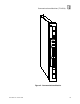

Communications Modules
(T3150A)
6
Industrial Control Services
Application
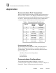
Communications Port Connections
Each communications port has a DB
-
25, female connector on
the front of the module. The RS232 and RS422/485 signals
are internally connected to the DB
-
25 connector pins as shown
in Table
1
. Refer to Figures
3
through
5
for recommended
communications cable requirements and connections.
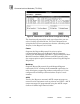
Table
1
. Communications Port Pin
-
out.
Pin No.
RS232
Signal
RS422/485
Signal
2
TX
(not used)
3
RX
(not used)
7
GND
GND
9
(not used)
+ 5 VDC
10
(not used)
TX (
-)
11
(not used)
RX (
-)
22
(not used)
TX (+)
23
(not used)
RX (+)
Recommended Ca
ble Type
For multidrop and Guarded Peer
-
Link communications a
Belden cable type 813x (where x = number of pairs) is
recommended. The cable has the following characteristics
that are important:
120 Ohm, Characteristic Impedance
Twisted Pairs
Overall shield
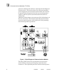
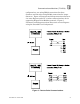
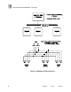
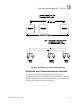
Communications Configurations
The communications module supports a variety of
communications configurations which are shown in Figures
3
through
5
. Figure
3
illustrates two point
-
to
-
point