User Manual
Manuals
Brands
Rockwell Automation Manuals
Equipment
T3150A ICS Regent Communications Module
11
12
13
14
15
16
17
18
19
20
Communications Modules
(T3150A)
PD
-
6002
Mar
-
06
17
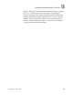
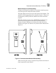
Figure
9
. Jumper Locations.
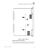
Module Assembly and Installation
Position the printed circuit board on the metal frame, guiding
the two 96
-
pin DIN connectors through the slots in the frame.
1
...
...
15
16
17
18
19
20
...
21