ICS Regent ® PD-6002 Communications Modules RS-232, RS-422 and RS-485 (T3150A) Issue 1, March, 06 Communications modules provide a serial communications interface between the controller and external equipment. Communications modules are commonly used to connect the controller to the computer running the WINTERPRET application, serial printers, man-machine interfaces, distributed control system gateways, and other peer-to-peer controllers. Features · Two isolated serial ports per module.
Communications Modules (T3150A) processor modules and combines it through a diode OR powersharing circuit. This ensures that if one processor module's power supply fails, the communications module will continue to operate by drawing power from the two remaining power supplies, and the system's communications functions are maintained. Additional isolated power converters provide isolated power to the two serial ports.
Communications Modules (T3150A) every millisecond to read characters from or write characters to the communications module. When the processor modules read characters from the communications module, the communications module sends characters through triplicated bus drivers to the processor Safetybus. The processor modules vote this triplicated data and perform communications processing.
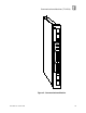
Communications Modules (T3150A) are checked by the processor modules’ normal communications processing. Failures result in a COMM module error indication at the processor modules and a COMM error at the communications module. Front Panel Figure 2 shows the physical features of the communications modules. The front panel of each module contains indicators showing overall module health, and the transmit and receive status of each channel.
Communications Modules (T3150A) Figure 2. Communications Module.
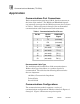
Communications Modules (T3150A) Application Communications Port Connections Each communications port has a DB-25, female connector on the front of the module. The RS232 and RS422/485 signals are internally connected to the DB-25 connector pins as shown in Table 1. Refer to Figures 3 through 5 for recommended communications cable requirements and connections. Table 1. Communications Port Pin-out. Pin No.
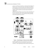
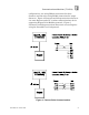
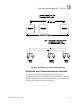
Communications Modules (T3150A) configurations, one using RS232 connections for short distances and the other using RS422 connections for longer distances. Figure 4 illustrates multidrop connections between 2 or more Regents and a PC or other communications device supporting Regent R2 or Modbus protocols. Figure 5 illustrates multidrop connections between 2 or more Regents using the Guarded Peer-Link protocol. Figure 3. Point-to-Point Communications.
Communications Modules (T3150A) Figure 4. Multidrop Communications.
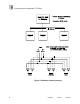
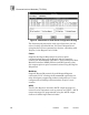
Communications Modules (T3150A) Figure 5. Guarded Peer-Link Communications. Protocols and Communications Functions The protocol and function supported for each port is configured using the Serial Ports command from the Project Editor’s Definitions menu in WINTERPRET. An example of the Serial Ports dialog is shown in Figure 6.
Communications Modules (T3150A) Figure 6. WINTERPRET’s Serial Ports Configuration Dialog. The function and protocol for each type of port that you can select is briefly described below. For more information on using the Serial Ports command see Section 4, Working with Projects, in the Regent User’s Guide. Comm Supports the Regent R2 protocol for point-to-point communications between the Regent and the computer running the WINTERPRET application.
Communications Modules (T3150A) Net Master/Net Slave Used by the Regent for Guarded Peer-Link communications to other multidrop Regents. These ports require a node number. Modbus Supports connection to external Modbus communications equipment that acts as a Modbus Master (the Regent is a Modbus Slave). A Modbus port supports the Modbus RTU protocol. Modbus ports can be used in point-to-point or multidrop configurations. These ports require a node number.
Communications Modules (T3150A) Table 2. Communication Module Jumper Settings.
Communications Modules (T3150A) Regent. With each communications module’s jumper settings the same, module replacement is simpler. A single spare module can replace any communications module without the need to position the jumpers specifically for “end” or “middle” Regents before replacement. Refer to the communications port pin numbers shown in Figure 7 to determine the proper external connection of the resistors.
Communications Modules (T3150A) Figure 7. RS422/485 Internal Signal Resistors. To change the jumper settings the communications module must be removed from the controller chassis and disassembled.
Communications Modules (T3150A) Module Removal and Disassembly Using a small slotted screwdriver, loosen the retaining screw near the top of the communications module. Pull open both removal levers on the front of the module. The module will disengage from the controller chassis. When it is disengaged, carefully slide the module out of the controller chassis. With the module removed, use a #2 Phillips screwdriver to remove the two screws from the left side of the module.
Communications Modules (T3150A) Refer to Table 2 to identify the proper jumper settings for your application’s communications configuration. Position the jumpers as needed on the module. Figure 9 shows the locations of the jumpers on board the module. Note: When shipped from the factory, no jumpers are installed on E131, E132, E133, E231, E232 and E233. For multidrop configurations you will need two jumpers for each port (such as E131 and E133 for port 1).
Communications Modules (T3150A) Figure 9. Jumper Locations. Module Assembly and Installation Position the printed circuit board on the metal frame, guiding the two 96-pin DIN connectors through the slots in the frame.
Communications Modules (T3150A) From the right side of the module, align the four holes in the printed circuit board wit four metal standoffs. Insert and tighten the four screws removed from the right side of the module. Turn the module over and install the two screws removed from the left side of the module. Visually inspect the connector at the back of the communications module for bent pins. If any pins are bent do not install the module. Do not try to straighten bent pins.
Communications Modules (T3150A) Maintenance No periodic maintenance or calibration is required for the digital input modules. There are no user replaceable parts inside these modules. Failed modules can be hot replaced. If the module being replaced has been configured to support multidrop connections be sure to check the jumper settings and properly configure the new module’s jumpers before installing it.
Communications Modules (T3150A) Specifications Power Requirements No external power required (powered by triplicated processor modules) Number of Serial Ports Two Serial Port Types RS-232, RS-422, and RS-485 Baud Rates 300 to 19,200 Communications Protocols Regent R2 Modbus RTU ASCII Output Guarded Peer-Link Serial Port Connector Module: Cable: DB-25, female DB-25, male Isolation 1000 volts minimum (serial device to logic) 1000 volts minimum (serial port to serial port) Heat Dissipation 7 Wa
Communications Modules (T3150A) Electromagnetic Interference • • • IEC 801 Part 2 - Electrostatic Discharges IEC 801 Part 3 - Radiated Electromagnetic Fields IEC 801 Part 4 - Transients and Bursts Safety Level 3: Contact discharge of 6 kV Level 3: 10 V/M, 27 MHz 500 MHz Level 4: 2 kV, 2.5 kHz for t = 60 sec Certified to DIN V VDE 0801 for Risk Class 5. Also designed to meet UL 508 and CSA 22.2, No. 142-M1981 Dimensions Height: Width: Depth: Weight PD-6002 Mar-06 13.0" (330 mm) 1.5" (38 mm) 9.