ICS Regent ® PD-6000 Processor Modules 110 VAC, 220/240 VAC and 24 VDC (128K: T3110, T3111 and T3112) (512K: T3120, T3121 and T3122) Issue 1, March, 06 The controller assembly's three processor modules store and execute application programs, scan and update the I/O modules, process communications, and detect system faults. Each of the processor modules executes the application programs independently, but in lock-step synchronization with the other two.
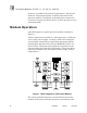
Processor Modules (T3110, 11, 12, 20, 21, and 22) faults are recorded in the system's fault history. Permanent faults are also annunciated by an LED on the front of the processor module. In addition, redundant fault contacts are activated to signal an external device to alert operators to any permanent fault. Module Operation A block diagram of a typical processor module is shown in Figure 1. Inside each processor module is a main processor, an I/O processor, and a power supply.
Processor Modules (T3110, 11, 12, 20, 21, and 22) permanent faults as they occur. All faults are recorded in the system's fault history. Each processor module contains its own power supply that converts input power to the logic power levels used by the internal processor circuits. The failure of one power supply will only effect one processor module — allowing the other two modules to continue operating — thus keeping the Regent online by virtue of its majority two-out-of-three voting architecture.
Processor Modules (T3110, 11, 12, 20, 21, and 22) while the I/O processors in each module read and write I/O synchronously. During these synchronous operations, all instructions and data are distributed across the Safetybus where automatic voting and fault detection occur. Main Processor During each scan cycle, the main processor executes application programs, reading inputs from the shared RAM and writing outputs to the shared RAM.
Processor Modules (T3110, 11, 12, 20, 21, and 22) • Fault filtering and reporting (which are available through WINTERPRET’s fault status and fault history features). Testing and Diagnostics Each processor module’s error detection logic is periodically tested to ensure its continued correct operation. Testing is done using self-tests that are automatically scheduled by each processor module’s real-time operating system.
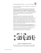
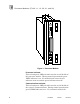
Processor Modules (T3110, 11, 12, 20, 21, and 22) Figure 3. Processor Module. Processor Indicator This red and green LED pair indicates the overall health of the processor module. During normal operation the green PROC indicator is on. If a module fault occurs the red indicator turns on and the green indicator turns off. Communications Indicator This red and green LED pair indicates the overall health of the system’s communications. During normal operation the green COMM indicator is on.
Processor Modules (T3110, 11, 12, 20, 21, and 22) occurs the red COMM indicator turns on and the green COMM indicator turns off. I/O Indicator This red and green LED pair indicates the overall health of the system’s I/O. During normal operation the green I/O indicator is on. If an I/O fault occurs the red I/O indicator turns on and the green indicator turns off. An I/O module failure causes all of the processor modules to indicate an I/O fault.
Processor Modules (T3110, 11, 12, 20, 21, and 22) Power Indicator The green POWER indicator is on when the module is receiving adequate power and its internal power supply is healthy. Reset Button A reset button is used to initiate the voted reset function. A voted reset clears system fault indicators after a fault has been detected and a module has been removed and replaced. Pressing the reset buttons on two operating modules performs a voted reset.
Processor Modules (T3110, 11, 12, 20, 21, and 22) Application Processor module type should be selected based on the main input power voltage (110 VAC, 220 VAC, or 24 VDC) and on memory requirements (128 kbytes or 512 kbytes). Each memory size supports all programming functions and up to 16 chassis of I/O. Typically, systems with more that 300 I/O points will require 512 kbytes of memory due the larger program size, increased data handling, etc.
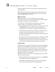
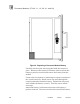
Processor Modules (T3110, 11, 12, 20, 21, and 22) Figure 4. Replacing a Processor Module Battery. Carefully cut the nylon wire wrap that holds the battery in place. Disconnect the battery lead button connector from the battery's positive terminal and remove the battery from the module. Connect the new battery by mounting its negative terminal to the circuit board clip. Attach a new wire wrap through the circuit board and around the battery. Tighten the wire wrap until it holds the battery securely.
Processor Modules (T3110, 11, 12, 20, 21, and 22) lead button connector as they may short-circuit the battery. You should be able to install the connector without tools. Reinstall the processor module in the controller chassis and perform a voted reset to initialize the module. EPROM Replacement EPROM replacement is necessary only when upgrading to a new version of the TRIOS operating system.
Processor Modules (T3110, 11, 12, 20, 21, and 22) Figure 5. Processor Module Disassembly. Loosen and remove the two screws securing the circuit board assembly to the metal frame. Remove the three cylindrical metal spacers and place them to one side. Lift the two circuit boards from the metal frame. The top circuit board (with the Motorola 68000 processor and two EPROMs in blue chip sockets) is the main processor board.
Processor Modules (T3110, 11, 12, 20, 21, and 22) this ribbon cable; instead, simply lift the main processor board to expose and access the I/O processor board. Figure 6. Processor Circuit Board Assembly. Replacing EPROMs The three EPROMs in each module are labeled U42 and U43 (main processor) and U19 (I/O processor). Figure 7 shows the locations of the EPROMs on each printed circuit board.
Processor Modules (T3110, 11, 12, 20, 21, and 22) Figure 7. Processor Module EPROM locations. Remove EPROM U42 from the main processor board by rotating the chip socket’s retaining clips outward. This will eject the chip from its socket. Remove the old EPROM and place it on antistatic foam off to one side.
Processor Modules (T3110, 11, 12, 20, 21, and 22) Remove the new U42 EPROM from its packaging and inspect its pins to make sure they are not bent. Find the pin one index point (or notch) on the new EPROM. Position the new EPROM in the chip socket so that the pin one index point is facing the U42 label on the printed circuit board. Carefully insert the new EPROM into the chip socket.
Processor Modules (T3110, 11, 12, 20, 21, and 22) Module Assembly Carefully align the main processor and I/O processor boards on their metal frame, guiding the four 96-pin DIN connectors through the slots in the metal frame. Slide the three cylindrical metal spacers through the holes in the two boards. Slide the two medium length panhead screws into the screw holes and partially tighten (do not fully tighten the screws yet). Check the alignment of the three cylindrical metal spacers.
Processor Modules (T3110, 11, 12, 20, 21, and 22) board. Carefully tuck any excess wire or ribbon cable down into the module (so neither will be in the way when you reinstall the module). Reinstalling Modules Reinstall the modules one at a time. To help make alignment easier, install the first processor module in the left-most position, the second module in the center position, and the third module in the right-most position. Hold the module by its handle, supporting it from underneath if necessary.
Processor Modules (T3110, 11, 12, 20, 21, and 22) Safety Considerations Processor module catalog numbers T3110, T3112, T3120 and T3122 are TÜV certified for Risk Class 5 safety critical applications. Catalog numbers T3111 and T3121 (220 VAC powered modules) have not been certified as they do not meet the DIN VDE 0110 requirements for creepage and clearances.
Processor Modules (T3110, 11, 12, 20, 21, and 22) Memory Size 128K: 512K: T3110, T3111, T3112 T3120, T3121, T3122 Memory Type Battery-backed CMOS RAM Battery Type Li/SO2 Battery Life Under Load: Shelf Life: I/O Interface Cable Length: I/O Chassis: 6 months 10 years Triple redundant I/O Safetybus 150 cable feet (45 m), maximum 16 chassis, maximum Operating Temperature 0° to 60° C (32° to 140° F) Storage Temperature -40° to 85° C (-40° to 185° F) Operating Humidity 0 to 95% relative humidity, no
Processor Modules (T3110, 11, 12, 20, 21, and 22) Electromagnetic Interference • • • • • IEC 801 Part 2 - Electrostatic Discharges IEC 801 Part 3 - Radiated Electromagnetic Fields IEC 801 Part 4 - Transients and Bursts IEC 801 Part 5 - Surge Immunity ANSI/IEEE C37.90 - Surge Withstand Capability Safety Level 3: Contact discharge of 6 kV Level 3: 10 V/M, 27 MHz 500 MHz Level 4: 2 kV, 2.5 kHz for t = 60 sec Level 3: 2 kV 2.
Processor Modules (T3110, 11, 12, 20, 21, and 22) PD-6000 Mar-06 21