Quick Start PlantPAx System Application Templates System Release 3.
Important User Information Read this document and the documents listed in the additional resources section about installation, configuration, and operation of this equipment before you install, configure, operate, or maintain this product. Users are required to familiarize themselves with installation and wiring instructions in addition to requirements of all applicable codes, laws, and standards.
Table of Contents Preface About This Publication. . . . . . . . . . . . . . . . . . . . . . . . . . . . . . . . . . . . . . . . . . . . . 5 Before Using This Publication . . . . . . . . . . . . . . . . . . . . . . . . . . . . . . . . . . . . . . 6 Before You Begin . . . . . . . . . . . . . . . . . . . . . . . . . . . . . . . . . . . . . . . . . . . . . . . . . . 7 PlantPAx Quick Start Worksheet . . . . . . . . . . . . . . . . . . . . . . . . . . . . . . . . . . . 7 Additional Resources . . . . . . . . . .
Table of Contents Chapter 3 Start Using Your HMI Project Before You Begin. . . . . . . . . . . . . . . . . . . . . . . . . . . . . . . . . . . . . . . . . . . . . . . . . What You Need. . . . . . . . . . . . . . . . . . . . . . . . . . . . . . . . . . . . . . . . . . . . . . . . . . Follow These Steps . . . . . . . . . . . . . . . . . . . . . . . . . . . . . . . . . . . . . . . . . . . . . . . Observe the Template Structure . . . . . . . . . . . . . . . . . . . . . . . . . . . . . . . . . . .
Preface About This Publication The purpose of this quick start is to describe how to apply application templates to start development of your PlantPAx™ Process Automation System.
Preface Before Using This Publication You can use the tasks described in this publication only after first completing some prerequisite tasks. For example, you must have your workstations and servers installed and communicating on a network. Table 1 describes the prerequisites. The procedures in this quick start use the following software versions: • RSLogix™ 5000 software, version 20.x • FactoryTalk® View software, version 7.0.
Preface Before You Begin The beginning of each chapter contains the following information. Read these sections carefully before beginning work in each chapter: • Before You Begin – This section lists the steps that must be completed and decisions that must be made before starting that chapter. This section defines the minimum amount of preparation required before completing the current chapter. • What You Need – This section lists the tools that are required to complete the steps in the current chapter.
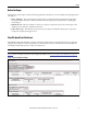
Preface Additional Resources These documents contain additional information concerning related products from Rockwell Automation. Resource Description Define and Procure PlantPAx Process Automation System Selection Guide, publication PROCES-SG001 Provides information to assist with equipment procurement for your PlantPAx system. 1756 ControlLogix Controllers Technical Data, publication 1756-TD001 Contains specifications for ControlLogix controllers.
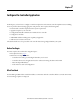
Chapter 1 Configure the Controller Application In this chapter, you learn how to configure controller templates that aid consistent controller implementation, including the use of periodic tasks and setting appropriate task priorities.
Chapter 1 Configure the Controller Application Figure 3 shows an example of the information required for this chapter based on a sample project using the PlantPAx Quick Start Worksheet. The worksheet is a useful aid in completing tasks in this chapter.
Configure the Controller Application Chapter 1 Follow These Steps The following tasks outlined below describe how to configure your template with a Logix5000 controller. You could already be familiar with many of these tasks, depending on your knowledge of Logix controllers. However, we suggest that you follow these steps to set up your controller for optimal performance of your PlantPAx system. The procedures in this chapter have to be completed for each controller in your project.
Chapter 1 Configure the Controller Application Controller Template Overview Controller templates provide the necessary task configurations that are required for the PlantPAx system. Controller template options also are provided with pre-loaded PlantPAx Library content if the PlantPAx Library is to be used. Library content definitions use controller memory, so use the guidance in Table 2 when selecting the appropriate template for your application.
Configure the Controller Application Chapter 1 Download the PlantPAx Library Follow these steps to download a controller template that is included in the PlantPAx Library of Process Objects. 1. Open the Knowledgebase Answer ID 62682 at http://www.rockwellautomation.custhelp.com. 2. Click the download link to access the zip files in the PlantPAx Library of Process Objects. 3. Select the V3.0 zip file and download the files to a folder.
Chapter 1 Configure the Controller Application Modify Controller Properties Follow these steps to modify the controller properties to associate the template to the target controller. 1. From the Edit menu, choose Controller Properties. 2. On the Controller Properties dialog box, type the name of the controller, slot number, and chassis type for the target controller. 3. Click Change Controller if your controller is not the type or firmware revision shown. Otherwise, skip to step 8.
Configure the Controller Application Chapter 1 4. From the Type pull-down menu, choose a controller IMPORTANT Refer to Table 2 on page 12 to make sure the controller has enough memory for the selected template. 5. From the Revision pull-down menu, choose your firmware revision. IMPORTANT The revision number for the firmware must match the version level of the software being used. For PlantPAx system release 3.0, select revision 20.
Chapter 1 Configure the Controller Application Configure Controller Task Rates The controller template contains nine predefined periodic tasks, eight of these named Task A…H. There is a separate periodic task named Controller Status, which is used to collect system diagnostics, for example, by using the L_CPU Add-On Instruction. Each task is set to execute at a defined time interval from 50 ms…10 s, with faster tasks getting higher priority.
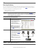
Configure the Controller Application Chapter 1 Add Modules to Local Chassis In this section, you are adding all the necessary modules to your local chassis, including network adapters and I/O modules, to the I/O tree of a Logix controller. 1. In the Controller Organizer, right-click the backplane and choose New Module. 2. In the Search field, type a catalog number of a module that you are adding. The example shows a 1756-EN2T network adapter being selected.
Chapter 1 Configure the Controller Application If applicable for your selected module, from the Major Revision pull-down menu, choose a firmware revision. 4. Click OK. 5. On the New Module dialog box, type a module name, description, and slot number (and IP address if adding a communication module). TIP Make sure the slot number for the module in the chassis is correct. 6. Click OK. 7. Repeat step 1 through step 6 to add each module in the local chassis of the target controller.
Configure the Controller Application Chapter 1 3. Type the Ethernet address for the module in the chassis. 4. Click OK. 5. Repeat step 1 through step 4 to configure each network adapter in the local chassis of the target controller. Configure I/O Modules Follow these steps to configure local analog and digital I/O modules with a Requested Packet Interval (RPI) and module definition, if applicable. The RPI is the amount of elapsed time for an exchange of data between the controller and module. 1.
Chapter 1 Configure the Controller Application 5. Repeat step 1 through step 4 to configure each I/O module in the local chassis of the target controller. Add Remote I/O Chassis and Modules Follow these steps to add the remote I/O chassis and associated I/O modules for the target controller. 1. In the I/O Configuration tree, right-click the remote I/O network adapter and choose New Module. 2. Type a catalog number to search for the network adapter in the remote I/O chassis. 3.
Configure the Controller Application Chapter 1 Download the Project Follow these steps to download your project to a controller. 1. Make sure your controller is in Remote Program mode. 2. If necessary, set a path to the controller. a. Click the Who Active icon. b. In the Who Active dialog box, navigate to your controller and click Set Project Path. 3. Click Download.
Chapter 1 Configure the Controller Application 4. Click Download again. Your project is downloaded to your controller. 5. Place your controller in whatever mode is necessary. For example, if you want the controller in Remote Run mode, from the Mode pull-down menu Run Mode. 6. When finished, save the file to a convenient location. IMPORTANT 22 Repeat the tasks in this chapter for the next controller, if applicable, starting on page 13.
Chapter 2 Create Your HMI Project In Chapter 1, you learned how to structure the controller application for your system. In this chapter, you create your HMI project to follow PlantPAx system recommendations by using the PlantPAx HMI templates.
Chapter 2 Create Your HMI Project The server section of the worksheet is a useful aid for completing tasks in this chapter.
Create Your HMI Project Chapter 2 Follow These Steps These steps describe how to create your HMI project.
Chapter 2 Create Your HMI Project HMI Template Overview There are three HMI templates available for download on the Knowledgebase Answer ID 62682 at http://www.rockwellautomation.custhelp.com. For most systems, you load the templates on the PASS server by using the EWS, and your system data is viewed on the OWS. Table 5 - HMI Template Names and Display Resolutions Name Supported Resolution FTVSE_7_P1FHD_3_0_00.apa 1920 x 1080, Full HD FTVSE_7_P1SXGA_3_0_00.
Create Your HMI Project Chapter 2 2. Click Site Edition (Local Station) and click Next. 3. Click Restore application and click Next. 4. Click Browse (…).
Chapter 2 Create Your HMI Project 5. Select a template .apa file that you want to restore and click Open. 6. Leave the default file location and click Next. 7. Type an application name and click Finish.
Create Your HMI Project Chapter 2 Create Your HMI Project To create your HMI project, in FactoryTalk View Studio software, first you create the network distributed or network station application, and then you add elements such as areas, HMI servers, Data servers, and Tag Alarm and Event servers. You assign the servers to their associated PASS servers. Follow these steps to create your application. 1.
Chapter 2 Create Your HMI Project Deploy Your HMI Template In this section, you use your HMI template to create your HMI servers. Your HMI project puts each logical server into its own area. The HMI server stores project components, such as the graphic displays, and provides the components to the OWSs upon request. 1. To create a new area, right-click the application name and choose New Area. 2. Type a name and description for the area and click OK. The area is added to your application.
Create Your HMI Project Chapter 2 4. Click Import a project and click Next. 5. On the FactoryTalk View message box, click OK. 6. From the Project type pull-down menu, choose FactoryTalk View Site Edition Project. 7. Click Browse (…) to locate the file path of the template you named on the Application Manager dialog box on page 28.
Chapter 2 Create Your HMI Project The file path appears in the Project file text box. 8. Click Next. 9. Type a name and description of the server. 10. From the Computer pull-down menu, choose the PASS server that is to host the HMI server. 11. Click Finish. All the HMI template files are loaded into the PASS server. 12. Repeat step 1 through step 11 for each HMI server in your project.
Create Your HMI Project Chapter 2 Configure Your Data Servers In this section, you learn how to initiate a Data server, which provides communication between the process controllers and the servers. Follow these steps to configure a Data server. 1. Right-click the main application area created for the associated HMI server and choose New Area. 2. Type a name and description of the Data server area. 3. Click OK.
Chapter 2 Create Your HMI Project 4. Right-click the Data server area and choose Add New Server>Rockwell Automation Device Server (RSLinx Enterprise). 5. Type a description of the Data server. 6. Click Browse and select the PASS server that is to host the Data server.
Create Your HMI Project Chapter 2 7. On the RSLinx Enterprise Server Properties dialog box, click the Alarms and Events tab. 8. To disable device-based alarming, clear the Enable alarm and event support checkbox. IMPORTANT The PlantPAx system sizing rules and critical system attributes are based on tag-based alarms. Therefore, we recommend a limited usage of device-based alarms. If device-base alarming is to be used, make sure additional loading has been considered.
Chapter 2 Create Your HMI Project 3. Click OK. 4. Right-click the alarm server area and choose Add New Server>Tag Alarm and Event Server. 5. Type a name and description for the Alarm and Event server. 6. From the Computer pull-down menu, choose the PASS server that is to host the Tag Alarm and Event server.
Create Your HMI Project Chapter 2 7. Click the Priorities and History tab. 8. Check the Enable history checkbox to enable alarm and event history. 9. From the Database definition pull-down menu, choose the alarm history database that was created during the installation of the FactoryTalk View SE software. IMPORTANT The alarm history database requires a separate SQL server installation. If there is no database selection available under Alarm and Event History, a database must be created.
Chapter 2 Create Your HMI Project Add Controllers to Data Server In this section, we create device shortcuts on Data servers so controllers can be connected. 1. In the project tree, click ‘+’ to expand the RSLinx Enterprise data server and double-click Communication Setup. 2. In the Device Shortcuts pane, click Add. 3. For the shortcut name, type the controller name. 4. In the Primary pane, expand the Ethernet driver to select the controller. 5. Click Apply.
Create Your HMI Project Chapter 2 6. On the message box, click Yes to apply changes to the shortcut. 7. Repeat step 1 through step 6 for each Data server and controller combination in your application.
Chapter 2 Create Your HMI Project Set Runtime Security If you are using the PlantPAx library, you must set up your runtime security to provide each account or group with the correct FactoryTalk View software security codes. These security codes verify that the correct permissions are provided to the operator, maintenance personnel, and engineer on the PlantPAx library faceplates. The PlantPAx library provides guidance on the proper maintenance of the security codes.
Chapter 3 Start Using Your HMI Project In this chapter, you examine the template structure and then create a FactoryTalk View SE software client file for your OWS. You also become familiar with the features of your HMI template. Before You Begin You must complete these tasks before using this chapter: • Tasks described in Before Using This Publication on page 6 • Load a template and create an HMI project; see Chapter 2 for procedures. What You Need FactoryTalk View SE software, version 7.
Chapter 3 Start Using Your HMI Project Follow These Steps These steps describe how to configure your HMI project.
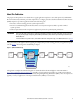
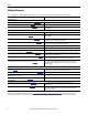
Start Using Your HMI Project Chapter 3 Observe the Template Structure The example tree diagram shows the HMI template structure. Display and start-up macros are created as part of the template (shown at the bottom of the example). The displays included in the template have the following naming structure: • (FRAME) is a prefix used on items intended only to be used as is with minimum customization. These may be instantiated to create different environments on large projects.
Chapter 3 Start Using Your HMI Project Create Your OWS Client File In this section, you create a FactoryTalk View SE client file. Client files are used to launch a FactoryTalk View software client from the OWS. Once created, this client file can be copied to each OWS. 1. From the FactoryTalk View Studio software Tools menu, choose Launch SE Client. 2. To create a new client file, click New. 3. From the FactoryTalk View SE Client Wizard dialog box, click New. 4.
Start Using Your HMI Project Chapter 3 5. Click Network Distributed or Network Station and click Next. 6. From the pull-down menu, choose the name of the application. 7. Click Next.
Chapter 3 Start Using Your HMI Project 8. From the Startup macro pull-down menu, choose a startup macro. The startup macro launches the initial displays and docks the navigation and alarm tool bars. 9. Click Next. 10. Check Maximize window and click Next. Make sure your selections in the check boxes match the dialog box as shown below. 11. From the FactoryTalk View SE Client Auto Logout dialog box, click Next.
Start Using Your HMI Project Chapter 3 12. Click Save configuration and open FactoryTalk View SE Client now, and click Finish. When the client file opens, your application window (example below) appears with the layout of the selected template.
Chapter 3 Start Using Your HMI Project Explore Template Features This section shows display navigation for your HMI project. We suggest you familiarize yourself with these features to enhance productivity with your templates. IMPORTANT Actual layout varies depending on the HMI template selection and the revision being applied. Alarm Tools Click the bell icon to access active alarms. Additional icons appear to access an alarm summary, alarm history, shelved alarms, and an alarm explorer.
Start Using Your HMI Project Chapter 3 System Status Click the System Status icon to view system diagnostics. Fort more information on diagnostics, see Chapter 4. System Status Navigation Tools There are three quick screen navigation buttons: Next, Previous, History. Forward/Backward/History The Display Navigation Map icon lets you move around your application faster. This feature is typically used for applications that have more than 10 displays.
Chapter 3 Start Using Your HMI Project The Administrator icon and security codes. accesses information about the system including display element sizes and version numbers The View Security icon accesses the Current Security Access display that shows the security level of the current user. This is a view-only display. A user’s security cannot be changed from this display. The Repaint/Repair icon can be used when making edits to an application.
Chapter 4 Add Basic System Diagnostics In this chapter, you learn how to add controller and PASS server diagnostics to your system health screen that is provided in the HMI template. As you develop your project, you can add additional diagnostics for your system. Add These Additional Resources are listed at the end of this chapter.
Chapter 4 Add Basic System Diagnostics Follow These Steps These steps describe how to configure your system diagnostics.
Add Basic System Diagnostics Chapter 4 Download the PlantPAx Library If you have not done so already, complete the task on page 13 to download the Logix diagnostic objects from the PlantPAx Library of Process Objects. TIP The diagnostics that you need to complete tasks in the next section are distributed with the Library in the Logix Diagnostic Objects Library folder.
Chapter 4 Add Basic System Diagnostics 5. Select the L_CPU L5X file based on your controller revision and click Import. 6. On the Import Configuration dialog box, click OK to create all of the tags and data types that are required for the Add-On Instruction. 7. Click Import Logic Edits as Pending and click OK.
Add Basic System Diagnostics Chapter 4 8. Type the controller slot number in the MOV instruction. 9. Change the GSV instruction to a CLR instruction that is configured as shown in the illustration. 10. Click the Finalize All Edits in Program icon . 11. Click Yes to finalize all of the edits. Add Controller Diagnostics to a HMI Project Follow these steps to add controller diagnostics to your HMI project. 1. Open the project that you created in Chapter 2 in the FactoryTalk View Studio software.
Chapter 4 Add Basic System Diagnostics 4. From your HMI project, right-click Logix Graphics Library and choose Open. 5. Right-click the controller graphic in the L_CPU box and choose Copy.
Add Basic System Diagnostics Chapter 4 6. On the P1f System display, right-click anywhere in the window and choose Paste. 7. Right-click the L_CPU graphics on the P1 System display and choose Global Object Parameter Values.
Chapter 4 Add Basic System Diagnostics 8. Type a shortcut name for the controller and click OK. TIP Make sure that you put the controller name inside brackets [ ] as shown. 9. Save the display. 10. Open the HMI template that you created in Chapter 3.
Add Basic System Diagnostics Chapter 4 11. On the HMI display, click the System Status icon. System Status On the HMI template, the controller graphic has some animation showing the position of the key switch and controller status indicators.
Chapter 4 Add Basic System Diagnostics 12. Click the controller to access the controller status faceplate. Home Tab Maintenance Tab Communication Tab Connections Tab CPU Usage Tab Controller Memory Tab Tabs on the faceplate also include information on the CPU usage and the status of controller memory and connections. For complete details, see the PlantPAx Library of Logix Diagnostic Objects, publication PROCES-RM003.
Add Basic System Diagnostics Chapter 4 Configure PASS Server Status In this section, you learn how to add diagnostics for your PASS servers. These diagnostics provide information on the software components that run on the PASS, including a HMI server, data server, and alarms and events server. 1. Open Knowledgebase Answer ID 44624 at http://rockwellautomation.custhelp.com and download the zip attachment. 2. Right-click the file and choose Open.
Chapter 4 Add Basic System Diagnostics 3. Right-click server status-state cpr9 and choose Extract All. The example shows the unzipped files. 4. In the FactoryTalk View HMI template, right-click Displays and choose Add Component Into Application.
Add Basic System Diagnostics Chapter 4 5. Open the server status-state cpr9 V505.gfx file from the files that were unzipped in step 3. 6. Right-click the imported display and choose VBA Code. 7. Find the text circled in the example and type the name of your HMI server and data server. 8. Save the changes to the VBA code and close the server status display. 9. Open a system display. For example, P1x.
Chapter 4 Add Basic System Diagnostics 10. From the Objects menu, choose Push Button>Button. 11. Click the display and drag the mouse to draw a button. 12. Click Browse (…) next to Release action.
Add Basic System Diagnostics Chapter 4 13. From the All Commands and Macros list, select Display and click Next. 14. From the File pull-down menu, choose the server status screen. 15. Click Finish.
Chapter 4 Add Basic System Diagnostics 16. On the Button Properties dialog box, click the Up Appearance tab. 17. In the Caption text box, type Server Status. 18. Click OK. 19. Save the changes to the P1 System display. 20. Run the client file and access the System Status page. 21. Click Server Status.
Add Basic System Diagnostics Chapter 4 The Server Status faceplate appears. The example shows a networked station application with the FactoryTalk server, HMI server, and data server on one workstation. None of the servers is redundant in this application example. TIP We recommend that diagnostic alarms for network adapters and I/O modules be added to the Alarm server to be displayed on the alarm banner and included in the alarm log and history.
Chapter 4 Add Basic System Diagnostics Notes: 68 Rockwell Automation Publication PROCES-QS001A-EN-P - October 2013
Appendix A Access the Quick Start Worksheet The Microsoft Excel file attached to this PDF file contains a worksheet that you can use to gather information required for executing the quick start. To use the Excel file, click the Attachments link (the paper clip icon) and double-click the Excel file. Enable Content Verify that macros are enabled when using the file. If this is the first time you are opening a Microsoft Excel file, you need to enable macros, if prompted. Click Enable Content.
Appendix A Access the Quick Start Worksheet Using the Worksheet The worksheet is a macro-enabled spreadsheet that contains entry fields. As information is entered, additional entry fields are dynamically created to collect more information.Where possible, some fields are auto-populated and entries are verified automatically. When completed, the worksheet must be saved as an Excel workbook (.xlsm) without the macros enabled.
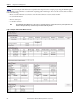
Access the Quick Start Worksheet Appendix A Figure 7 - Controller Detail Worksheet Rockwell Automation Publication PROCES-QS001A-EN-P - October 2013 71
Appendix A Access the Quick Start Worksheet Figure 8 - PASS Worksheet 72 Rockwell Automation Publication PROCES-QS001A-EN-P - October 2013
Access the Quick Start Worksheet Appendix A Figure 9 - PASS Worksheet (continued) Rockwell Automation Publication PROCES-QS001A-EN-P - October 2013 73
Appendix A Access the Quick Start Worksheet Notes: 74 Rockwell Automation Publication PROCES-QS001A-EN-P - October 2013
Index A access worksheet file 69 adapters add network 18 add controller to data server 38 modules 17 remote chassis 20 additional resources 8 administrator access 50 alarm servers configuration 35 tools 48 application manager 26 C change controller type 14 module definition 19 chassis remote modules 20 client files HMI 44 CompactLogix controllers 12 configure alarm servers 35 controller diagnostics 53 controller templates 9 data servers 33 HMI servers 30 I/O modules 19 network adapters 18 controller add to
Index K Knowledgebase downloads 5 templates 5 L learn about HMI project 41 load HMI templates 26 M m 26 manual scope 5 map display navigation 49 modify controller properties 14 module add 17 add remote 20 change definition 19 N navigation display map 49 tools 49 network add adapters 18 O overview controller 12 HMI templates 26 P PlantPAx reference manual 6 preface 5 prerequisite HMI tasks 23 tasks 6 project create HMI 29 download 21 HMI familiarity 41 properties modify controller 14 quick steps contr
Index templates controller 12 controller configuration 9 deploy HMI 30 descriptions for controllers 12 explore HMI features 48 HMI names 26 HMI overview 26 HMI structure 43 Knowledgebase 5 load HMI 26 open controller 13 purpose 5 tools alarms 48 HMI templates 48 navigation 49 type change controller 14 V versions software 6 view security 50 W worksheet access file 69 controller example 10 quick start 7 server example 24 Rockwell Automation Publication PROCES-QS001A-EN-P - October 2013 77
Index Notes: 78 Rockwell Automation Publication PROCES-QS001A-EN-P - October 2013
Rockwell Automation Support Rockwell Automation provides technical information on the Web to assist you in using its products. At http://www.rockwellautomation.com/support you can find technical and application notes, sample code, and links to software service packs. You can also visit our Support Center at https://rockwellautomation.custhelp.com/ for software updates, support chats and forums, technical information, FAQs, and to sign up for product notification updates.