
User manual

44 Rockwell Automation Publication 1783-UM003I-EN-P - March 2014
Chapter 2 Getting Started
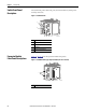
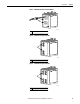
Switch Front Panel
Description
The switch front panel contains the ports, the status indicators, and the power
and relay connectors.
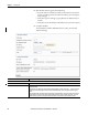
Figure 1 - 1783-MS10T Switch
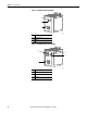
Expansion Module
Front Panel Descriptions
Figure 2…Figure 7 show the expansion module front panels.
Figure 2 - 1783-MX08T Switch Copper Expansion Module (side cover removed)
1 Power and relay connectors
2 Console port
3 Dual-purpose ports
4 10/100 ports
5 Protective ground connection
31826-M
1
2
3
4
5
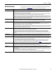
1 10/100 ports
31827-M
1