
User manual

Rockwell Automation Publication 1783-UM003I-EN-P - March 2014 31
Install the Switch Chapter 1
Wire the DC Power Source
for the PoE Expansion
Module (optional)
Power supply requirements for a PoE expansion module depend on your
application.
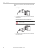
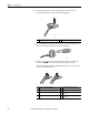
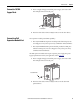
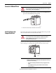
Follow these steps to wire DC power to the PoE expansion module.
1. Locate the power connector and identify the positive and return DC
power connections.
2. Measure a length of 0.82…0.52 mm
2
(18…20 AWG) copper wire long
enough to connect to the DC power source.
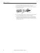
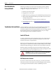
3. Use an 18-gauge wire-stripping tool to strip each of the two wires to
6.3 mm (0.25 in.) ± 0.5 mm (0.02 in.).
Do not strip more than 6.8 mm (0.27 in.) of insulation from the wire.
Stripping more than the recommended amount of wire can leave exposed
wire from the connector after installation.
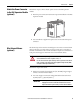
WARNING: Before performing any of the following procedures, make sure that
power is removed from the DC circuit or the area is nonhazardous before
proceeding.
WARNING: To comply with the CE Low Voltage Directive (LVD), this equipment
must be powered from a source compliant with the safety extra low voltage
(SELV) or protected extra low voltage (PELV).
To comply with UL restrictions, this equipment must be powered from a source
compliant with Class 2 or Limited Voltage/Current.
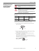
Application Power Consumption Power Supply per Port Allen-Bradley Products
PoE only
IEEE 802.3af
44…57V DC (48V DC nom) 15.4 W, max Switched mode power supplies:
• 1606-XL Standard
• 1606-XLE Essential
• 1606-XLP Compact
• 1606-XLS Performance
PoE and PoE +
IEEE 802.3at Type 2
50…57V DC (54V DC nom) 15.4 W, max for PoE
30 W, max for PoE+
32437-M
DC +
DC -
31784-M
6.8 mm (0.27 in.)