
User manual

28 Rockwell Automation Publication 1783-UM003I-EN-P - March 2014
Chapter 1 Install the Switch
Ground the Switch
Follow these steps to connect the switch to a protective ground.
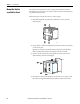
1. Use a screwdriver to remove the ground screw from the front panel of the
switch.
Store the ground screw for later use.
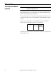
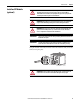
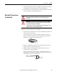
2. If your ground wire is insulated, use a wire stripping tool to strip the
5.3 mm
2
(10 AWG) ground wire to 12.7 mm (0.5 in.) ± 0.5 mm (0.02 in.).
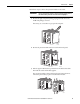
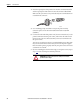
3. Insert the ground wire into the ring terminal lug.
4. Use a crimping tool to crimp the ring terminal to the wire.
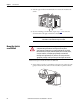
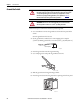
5. Slide the ground screw through the ring terminal.
6. Insert the ground screw into the ground-screw opening on the front panel.
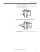
ATTENTION: For proper grounding, you must always connect the power supply
functional-ground screw when connecting the power supply. You must provide
an acceptable grounding path for each device in your application. For more
information on proper grounding guidelines, refer to publication
1770-4.1,
Industrial Automation Wiring and Grounding Guidelines.
ATTENTION: You must use the external grounding screw on the front of the
switch to ground the switch. Use a 5.3 mm
2
(10 AWG) ground wire.
31789-M
12.7 mm (0.5 in.)
31790-M
VRTAA
31791-M