
Quick Start 1/2-20HP NEMA 4X/12 Owner manual
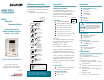


Terminal Assignments
Term.# Definition Default
1 Digital In #1 Stop/ Clr Flt
2 Digital In #2 Start
3 Digital In #3 Function Loss
4 Digital In #4 Jog
5 Digital In #5 Manual
6 Digital In #6 Speed Sel 1
7 +24VDC Int. Common
Logic
Input Supply
Terminals
8 Logic Input Common
9 +24VDC Output
10 +10VDC Ref. Supply
11 Relay Out #1 - NO
/Fault*12 Relay Out #1 - C
13 Relay Out #1 - NC
14 Analog In #1 Volts (-)
Not
Assigned
15 Analog In #1 Volts (+)
16 Analog In #1 (4-20ma)
Default 4-20 mA
Input
17 Analog In #1 (4-20ma)
18 Analog In #2 Volts (-)
Default 0-10 VDC
Input
19 Analog In #2 Volts (+)
20 Analog In #2 (4-20ma)
Not
Assigned
21 Analog In #2 (4-20ma)
22 Analog Common Analog Output
23 Analog Out Volts (+) Output Freq. (Hz)
24 Relay Out #2 - NO
Running*25 Relay Out #2 - C
26 Relay Out #2 - NC
D-2992
* Form C Relay contact outputs:
NO (Normally Open)
NC (Normally Closed)
C (Common)
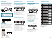
Reference Wiring
Analog Reference Wiring
(0 to 10 VDC Input)
(P90) Speed Ref A Sel = Analog In1
(P91) Speed Ref Hi = 60 Hz.
(P92) Speed Ref Lo = 0 Hz.
(P320) Analog In Config =..xx00
(P322) Analog In 1 Hi = 10.0 V
(P323) Analog In 1 L0 = 0.0 V
Analog Inputs can be configured for 4-20
mA. See instruction manual.
Analog Output Wiring
(0 to 10 VDC Output)
(P341) Analog Out Absolute = 1
(P342) Analog Out1 Sel = Output Freq.
(P343) Analog Out1 Hi = 10.0 V
(P344) Analog Out1 Lo = 0.0 V
10 14 15 22
+10 VDC
Analog In 1 (-)
Analog In 1 (+)
Common
C
om
m
on
A O
ut Volts
Control Wiring cont’d
Two Wire Start/Stop Control
(P89) Logic Source Sel = Terminal Block
(P361) Digital In1 Sel = Not Used
(P362) Digital In2 Sel = Run
(P363) Digital In3 Sel = Function Loss
Three Wire Start/Stop Control
(P89) Logic Source Sel = Terminal Block
(P361) Digital In1 Sel = Stop
(P362) Digital In2 Sel = Start
(P363) Digital In3 Sel = Function Loss
See Parameters P361 to P366 for
configuration of all logic inputs.
1 2 3 7 8 9
Run
Function Loss
Supply Com.
Logic Com.
+24 VDC
1 2 3 7 8 9
Start
Function Loss
Supply Com.
Logic Com.
+24 VDC
Stop
Power Wiring
Input Voltage: Determined by model
number. Voltage Class configures the
drive for International voltage supplies.
Control Wiring
Default: (Out-of-the-box) configuration
is for Keypad control. The user will be
able to start the controller using the
built-in drive mounted operator interface
module.
3 7 8 9
Function Loss
Supply Com.
Logic Com.
+24 VDC
Start
Stop
L1
R
L2
S
L3
T
+DC BRK T1
U
T2
V
T3
W
PE PE
M
BR1
BR2
ATTENTION: The SP600 does
not provide branch circuit
protection. The user must install
the proper protection devices.
!
Increase / Decrease Speed