
User Manual Version 1.0 Owner manual

6-8
SP600 AC Drive User Manual
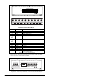
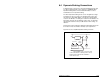
Terminal Description Notes
R R (L1) AC line input power
S S (L2) AC line input power
T T (L3) AC line input power
+DC
1
or
BR1
1
Early versions of the power terminal block are labeled +DC and BRK.
Later versions are labeled BR1 and BR2.
DB (+) Dynamic brake resistor connection (+)
BRK1
1
or
BR2
DB (-) Dynamic brake resistor connection (–)
U U (T1) To motor
V V (T2) To motor
W W (T3) To motor
PE PE Ground
PE PE Ground
-DC DC Bus (-)
May be located to the left or right of the
Power Terminal Block.
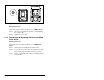
Figure 6.5 – Power Terminal Block
L1
R
L2
S
L3
T
BR1
+DC
BR2
BRK
T1
U
T2
V
T3
W
PE PE
-DC
-DC
➊
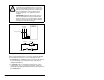
Frames A-D Power Terminal Block and DC Bus Test Points
L1
R
L2
S
L3
T
+DC –DC BR1 BR2 T1
U
T2
V
T3
W
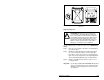
Frame E Power Terminal Block
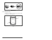
Figure 6.6 – Power Input Terminals on the Internal RFI Filter Option
L1
R
L2
S
L3
T
BR1
+DC
BR2
BRK
T1
U
T2
V
T3
W
PE PE
-DC
-DC
L1
R
L2
S
L3
T