
User Manual Version 1.0 Owner manual
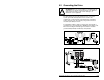

Wiring Requirements for the Drive
4-11
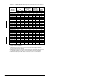
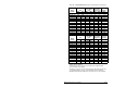
Table 4.6 – SP600 400/480 VAC Input Recommended Protection Devices
Model
Number
kW
Dual Element
Time Delay
Fuse
Non-time
Delay Fuse
Circuit
Breaker
1
ND HD Min
2
Max
3
Min
2
Max
3
Max
4
400 VAC Input
6SP401-1P1 0.37 0.25 3 3 3 5 15
6SP401-2P1 0.75 0.55 4 6 4 8 15
6SP401-3P4 1.5 1.1 6 6 6 12 15
6SP401-005 2.2 1.5 10 10 10 20 20
6SP401-008 4 3 15 17.5 15 30 30
6SP401-011 5.5 4 15 25 15 45 40
6SP401-014 7.5 5.5 20 30 20 60 60
6SP401-022 11 7.5 30 45 20 80 80
6SP401-027 15 11 40 60 40 120 120
6SP401-034 18.5 15 45 80 45 125 125
6SP401-040 22 18.5 60 90 60 150 150
6SP401-052 30 22 80 125 80 225 240
6SP401-065 37 30 90 150 90 250 280
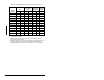
Model
Number
HP
Dual Element
Time Delay
Fuse
Non-time
Delay Fuse
Circuit
Breaker
1
ND HD Min
2
Max
3
Min
2
Max
3
Max
4
480 VAC Input
6SP401-1P1 0.5 0.33 3 3 3 4 15
6SP401-2P1 1 0.75 6 6 3 8 15
6SP401-3P4 2 1.5 6 6 6 12 15
6SP401-005 3 2 10 10 10 20 20
6SP401-008 5 3 15 15 15 30 30
6SP401-011 7.5 5 15 20 15 40 40
6SP401-014 10 7.5 20 30 20 50 50
6SP401-022 15 10 25 45 25 80 80
6SP401-027 20 15 35 60 35 100 100
6SP401-034 25 20 40 70 40 125 125
6SP401-040 30 25 50 90 50 150 150
6SP401-052 40 30 60 110 60 200 200
6SP401-065 50 40 80 125 80 250 250
1
Circuit Breaker - inverse time breaker. For US NEC, minimum size is 125% of motor FLA.
Ratings shown are maximum
2
Minimum protection device size is the lowest rated device that supplies maximum
protection without nuisance tripping.
3
Maximum protection device size is the highest rated device that supplies drive protection.
For US NEC, minimum size is 125% of motor FLA. Ratings shown are maximum.
4
Maximum allowable rating by US NEC. Exact size must be chosen for each installation.