
User Manual Version 1.0 Owner manual
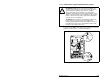


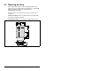

Mounting the Drive
3-11
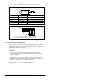
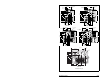
Figure 3.8 – SP600 Flange-Mount Bottom View Dimensions
72.4 (2.85)
59.6 (2.35)
96.1 (3.78)
101.9 (4.01)
40.7 (1.60)
51.3 (2.02)
103.2 (4.06)
22.2 (0.87) Dia.
4 Places
43.2
(1.70)
70.5
(2.78)
76.6
(3.02)
95.9
(3.78)
104.4
(4.11)
70.9 (2.79)
92.4 (3.64)
102.7 (4.04)
130.5 (5.14)
140.6 (5.54)
144.4 (5.69)
60.3 (2.37)
49.7 (1.96)
41.4
(1.63)
65.9
(2.59)
76.6
(3.02)
95.0
(3.74)
103.5
(4.07)
22.2 (0.87) Dia.
5 Places
53.1 (2.09)
73.0 (2.87)
92.2 (3.63)
111.2 (4.38)
64.7 (2.55)
75.4 (2.97)
129.3 (5.09)
40.6
(1.60)
68.7
(2.70)
94.6
(3.72)
102.9
(4.05)
22.2 (0.87) Dia.
4 Places
51.9 (2.04)
78.3 (3.08)
107.3 (4.22)
135.5 (5.33)
164.1 (6.46)
83.7 (3.30)
73.0 (2.87)
42.3
(1.67)
74.1
(2.92)
94.6
(3.27)
103.5
(4.07)
28.5 (1.12) Dia.
2 Places
22.2 (0.87) Dia.
2 Places
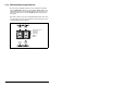
Frame A
Frame B
Frame C
Frame D
Dimensions in mm (in)
108.0 (4.25)
159.0 (6.26)
210.0 (8.27)
37.0
(1.46)
50.0
(1.97)
91.6
(3.61)
210.0 (8.27)
108.0 (4.25)
22.2
(0.87)
43.7
(1.72)
75.1
(2.96)
Frame E