
User Manual Version 1.0 Owner manual


13-2
SP600 AC Drive User Manual
.
Step 5. Once the drive has been serviced, reattach the drive’s
cover.
Step 6. Reapply input power.
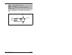
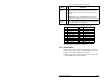
Measure the DC bus voltage at the +DC terminal
of the power terminal strip and the -DC test point.
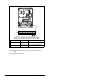
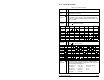
Figure 13.1 – Location of DC Bus Voltage Measuring Points
COMM PORT
CTRL BD
GND
UIB CONN
CONTROL/POWER CONN
WIRE
STRIP
CONTROL
POWER
Front View (Cover Removed)
L1
R
L2
S
L3
T
+DC BRK T1
U
T2
V
T3
W
PE PE
-DC
-DC
➊➋
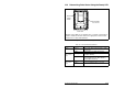
-DC Test Point Description Notes
DC Bus (-)
Location on A and B frames
DC Bus (-)
Location on C and D frames