
User Manual Version 1.0 Owner manual

Parameter Descriptions
12-79
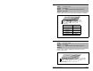
Parameter number whose value will be written to a communications
device data table. See figure 12.48.
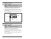
Selects the type of input signal being used for analog input 1 and 2.
These inputs can be configured as 10 VDC or 4-20 mA inputs. See
scaling parameters 322, 323 (Analog In1) and 325, 326 (Analog
In2).
316
317
Data Out D1 - Link D Word 1
Data Out D2 - Link D Word 2
Range: 0 to 387 [1]
Default: 0 (Disabled)
Access: 2 Path: Communication>Datalinks
See also:
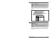
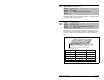
320 Anlg In Config
Range: See figure 12.49
Default: See figure 12.49
Access: 0 Path: Inputs & Outputs>Analog Inputs
See also: 322, 323, 325, 326
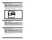
Figure 12.49 – Anlg In Config (320)
0xx 1xxxxxxxxxxxx
10 01234567891112131415
1 = Current
0 = Voltage
x =Reserved
Bit #
Factory Default Bit Values
Analog In 1
Analog In 2
Nibble 1Nibble 2Nibble 3Nibble 4
Analog In1 Bit Term
0 to 10 VDC Bit 0 = 0 14, 15
4 to 20 mA Bit 0 = 1 16, 17
Analog In2 Bit Term
-10 to +10 VDC Bit 1 = 0 18, 19
4 to 20 mA Bit 1 = 1 20, 21