
User Manual Version 1.0 Owner manual

Parameter Descriptions
12-73
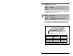
Displays the output state of the logic function control block resulting
from the combination of all port requests and masking functions.
Each bit or set of bits represent a command to the drive. Bit 6 will
always = 0.
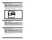
Displays the present frequency reference scaled as a DPI reference
for peer-to-peer communications. The value shown is the output
prior to the accel/decel ramp and any corrections supplied by slip
comp, PI, etc.
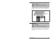
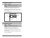
271 Drive Logic Rslt
Range: See figure12.43
Default: Read Only
Access: 2 Path: Communication>Comm Control
See also:
Figure 12.43 – Drive Logic Rslt (271)
0110000101110000
10 01234567891112131415
1 = Condition Active
0 = Condition Inactive
x =Reserved
Bit #
Stop
Start
Jog
Clear Fault
Forward
Reverse
Local Contrl
Mop Inc
Accel 1
Accel 2
Decel 1
Decel 2
Spd Ref ID 0
(1)
Spd Ref ID 1
(1)
Spd Ref ID 2
(1)
MOP Dec
Nibble 1Nibble 2Nibble 3Nibble 4
Bits
(1)
Description14 13 12
0
0
0
0
1
1
1
1
0
0
1
1
0
0
1
1
0
1
0
1
0
1
0
1
No Command - Man. Mode
Ref A Auto
Preset 2 Auto
Preset 3 Auto
Preset 4 Auto
Preset 5 Auto
Preset 6 Auto
Preset 7 Auto
272 Drive Ref Rslt
Range: 0 to 32767 [1]
Default: Read Only
Access: 2 Path: Communication>Comm Control
See also: