
User Manual Version 1.0 Owner manual
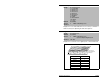

Parameter Descriptions
12-69
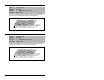
Captures and displays the Drive Alarm 1 at the time of the last fault.
See parameter 211 for the bit descriptions.
Captures and displays the Drive Alarm 2 bit pattern at the time of
last fault. See section 13.3 for the bit descriptions.
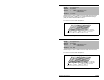
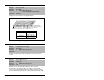
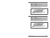
229 Alarm 1 @ Fault
Range: See figure12.39
Default: Read Only
Access: 2 Path: Utility>Diagnostics
See also: 211, 224-230
Figure 12.39 – Alarm 1 @ Fault (229)
00 x000x001xxxxxx
10 01234567891112131415
1 = Condition True
0 = Condition False
x =Reserved
Bit #
Prechrg Actv
UnderVoltage
Power Loss
Anlg in Loss
IntDBRes OH
Drv OL Lvl 1
Drv OL LVl 2
Decel Inhibit
Nibble 1Nibble 2Nibble 3Nibble 4
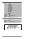
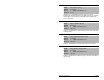
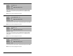
230 Alarm 2 @ Fault
Range: See figure12.40
Default: Read Only
Access: 2 Path: Utility>Diagnostics
See also: 211, 224-230
Figure 12.40 – Alarm 2 @ Fault (230)
00000000000xx00
10 01234567891112131415
1 = Condition True
0 = Condition False
x =Reserved
Bit #
DigIn CflctA
DigIn CflctB
DigIn CflctC
Bipolr Cflct
MtrTyp Cflct
NP Hz Cflct
MaxFrq Cflct
VHz NegSlope
IR Vlts Rang
FlxAmps Rang
SpdRef Cflct
Nibble 1Nibble 2Nibble 3Nibble 4
Dig In Value
UserSet Cflct
0