
Installation and Operation Manual Owner manual


Wiring the Drive
5-7
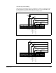
IET Reset Control Wiring
IET reset control wiring connects to terminals 8 and 11. See figures 5.5 and 5.6. Note
that these reset wiring connections are not to be used in multi-speed preset
applications. See figures 5.7 and 5.8.
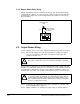
Forward/Reverse Control Wiring
Forward/reverse control wiring connects to terminals 9 and 11. See figures 5.5
through 5.7. Note that the setting of the forward/reverse switch is ignored when
parameter F-17 is equal to 1 (disable reverse operation).
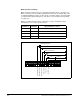
Function Loss Control Wiring
Function loss control wiring connects to terminals 10 and 11. See figures 5.5 through
5.7. Typically, a function loss input is a maintained, normally-closed pushbutton.
A signal must be present at terminal 10 for the drive to run. A factory-installed jumper
connects terminals 10 and 11 which provides that signal. Remove this jumper if a
function loss input, a coast-stop pushbutton, or another external interlock (for
example, a motor thermostat) is used. Removing the jumper allows the drive to stop
when the contact is open.
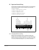
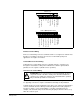
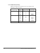
Figure 5.8 – Terminal Usage During Multi-Speed Preset Operation
!
ATTENTION:The user must provide an external, hardwired emergency
stop circuit outside of the drive circuitry. This circuit must disable the
system in case of improper operation. Uncontrolled machine operation
may result if this procedure is not followed.
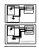
F-00 = 3 (Multi-Speed Presets)
4
4
Analog Meter Output
24 VDC Common
Stop
Start
IET Reset
Forward/Reverse
Function Loss
24 VDC Common
Snubber Resistor
Braking Signal
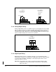
Analog Meter Output
24 VDC Common
Start/Stop/IET Reset
Multi-Speed Preset 2
Multi-Speed Preset 1
Forward/Reverse
Function Loss
24 VDC Common
Snubber Resistor
Braking Signal
F-00 = 0, 1, 2