
Quick Start Guide Manual

Drive Identification
1
Drive Identification
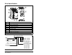
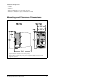
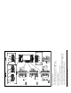
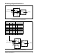
SP200 AC Drive Components
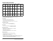
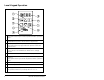
Model Number Structure
Item Description
1 Nameplate
2 OK (green) / Fault (red) LED
3 Control Signal Terminal Block
4 Motor Output Terminal Block
5Fan
6 Bottom Finger Guard
7 Optional Local Keypad
8 Top Finger Guard
9 AC Input Power Terminal Block
Enclosure Type
0 = Protected chassis
(Reserved - not used)
(Reserved - not used)
(Reserved - not used)
0 3P5 A1 0
SP200
Voltage
Input
Output
2 = 200-240 V, 3-phase; 230 V, 3-phase
4 = 380-480 V, 3-phase; 460 V, 3-phase
X = Selectable:
Y = 200-240 V, 1-phase; 230 V, 3-phase
100-120 V, 1-phase; 230 V, 3-phase
or
200-240 V, 1-phase; 230 V, 3-phase
Output Current (Horsepower)
1P3 = 1.3 A (0.5 HP)
2P0 = 2.0 A (1.0 HP)
2P3 = 2.3 A (0.5 HP)
3P5 = 3.5 A (2.0 HP)
4P2 = 4.2 A (1.0 HP)
6P0 = 6.0 A (1.5 HP)
7P0 = 7.0 A (2.0 HP)
S20 4
-
0 0
Model (Control Type)
A1 = Single Channel Analog
B1 = Preset Speed
C1 = Dual Channel Analog