Installing and Operating the SP200 AC Drive Remote Keypad Installation et utilisation de la console de commande et de programmation à distance du variateur de vitesse SP200 CA Montage und Betrieb der Fernbedienung für den Frequenzumrichter SP200 Installazione e uso del tastierino remoto per l’inverter SP200 Instalação e Operação do Teclado Remotodo Inversor CA SP200 Instalación y funcionamiento del teclado de control remoto del variador de velocidad SP200 de corriente alterna M/N S20-RK1 MODELE N° S20-RK1
The information in this manual is subject to change without notice. Throughout this manual, the following notes are used to alert you to safety considerations: ! ATTENTION: Identifies information about practices or circumstances that can lead to personal injury or death, property damage, or economic loss. Important:Identifies information that is critical for successful application and understanding of the product.
L’information contenue dans le présent manuel est susceptible d’être modifiée sans préavis. Tout au long du manuel, les remarques suivantes sont utilisées pour attirer l’attention de l’utilisateur sur un problème de sécurité : ! ATTENTION : Ceci identifie des renseignements concernant des usages ou des situations pouvant provoquer des dommages corporels ou entraîner la mort, causer des dégâts matériels ou une perte d’ordre économique.
Die in diesem Handbuch enthaltenen Angaben können ohne vorherige Ankündigung geändert werden. In diesem Handbuch werden die folgenden Hinweise verwendet, um auf Sicherheitsaspekte aufmerksam zu machen: ! ACHTUNG: Kennzeichnet Angaben zu Arbeitsweisen und Umständen, die zu Verletzungen oder sogar zum Tode sowie zu Sachschäden oder wirtschaftlichen Verlusten führen können. Wichtig:Kennzeichnet Angaben, die für die richtige Anwendung und das Verstehen des Produkts notwendig sind.
Le informazioni contenute in questo manuale sono soggette a cambiamenti senza preavviso. In tutto il manuale si trovano le seguenti note di avvertimento per la sicurezza dell’operatore: ! ATTENZIONE: identifica informazioni su modi di operare o su circostanze che possono causare infortuni a persone o morte, danni a beni di proprietà o perdita economica. Importante:identifica informazioni cruciali per la comprensione e l’uso adeguato del prodotto.
As informações contidas neste manual estão sujeitas a alterações sem aviso prévio. As notas seguintes são usadas neste manual para alertá-lo sobre considerações relativas à segurança: ! ATENÇÃO: Identifica informações sobre práticas ou circunstâncias que podem resultar ferimentos pessoais ou morte, dano de propriedade ou perda financeira. Importante:Identifica a informação que é essencial para uma aplicação bem-sucedida e o entendimento do produto.
La información de este manual está sujeta a cambios sin previo aviso. Las siguientes notas se utilizan en todo el manual para llamar la atención del lector hacia ciertos aspectos relacionados con su seguridad: ! ATENCIÓN: Indica información referente a prácticas o circunstancias que pueden causar lesiones o la muerte, daños a bienes o pérdidas económicas. Importante:Identifica información esencial para el uso correcto del producto y la comprensión adecuada del mismo.
English CONTENTS Chapter 1 About the Remote Keypad .................................... 1-1 1.1 Keypad Features................................................ 1-2 1.2 Display Description ............................................ 1-4 1.3 LED Descriptions ............................................... 1-4 1.4 Related Hardware .............................................. 1-5 1.5 Related Publications ..........................................1-5 1.6 Compatibility with Earlier Versions of the Drive .
English II SP200 AC Drive Remote Keypad
English List of Figures Figure 1.1 – Remote Keypad ......................................................... 1-1 Figure 1.2 – Keypad Features ....................................................... 1-2 Figure 2.1 – Remote Keypad Mounting Template......................... 2-2 Figure 2.2 – Mounting the Remote Keypad.................................... 2-3 Figure 2.3 – Connecting the Remote Keypad to the Drive ............ 2-4 List of Tables Table 1.1 – Model Number Contents .................................
English IV SP200 AC Drive Remote Keypad
English CHAPTER 1 About the Remote Keypad The Remote Keypad can be used to change parameter values, display operating conditions, and command drive operation. It connects to the drive’s circular mini-DIN connector via a connector cable (see section 1.4 for more information). It is compatible with all SP200 drive models (see section 1.6 for more information). Figure 1.1 shows the Remote Keypad. Refer to Appendix A for Remote Keypad dimensions. Figure 1.
English Table 1.1 provides a parts list for the Remote Keypad. Table 1.1 – Model Number Contents Description Qty Part Number Remote Keypad 1 — Gasket 1 42336-046-01 Instruction Manual 1 D2-3431 1.1 Keypad Features Figure 1.2 identifies the Remote Keypad keys, LEDs, and display features. Table 1.2 describes these Remote Keypad features. Sections 1.2 and 1.3 describe the keypad display and LEDs (labeled 9 and 10 in figure 1.2). 9 3 10 1 5 2 6 4 7 8 Figure 1.
English Table 1.2 – Keypad Features Description 1 The PROGRAM key toggles between display and program modes. The PROGRAM LED turns on when the drive is in program mode. 2 In display mode, the ENTER key scrolls through the display parameters. In program mode, this key toggles between the parameter number and parameter value. 3 In display mode, the UP ARROW key increments the local speed reference. In program mode, this key increments the parameter number or parameter value.
English 1.2 Display Description The keypad has a four-character display (labeled 9 in figure 1.2) which is used to show parameter numbers and parameter values. The keypad monitors its connection to the drive and will display if this connection fails due to electrical noise or a hardware failure. If the drive faults, the full display will flash to indicate the presence of the fault, and the fault code will be displayed.
English 1.4 Related Hardware The Remote Keypad connects to the SP200 AC Drive using a connector cable. This cable must be purchased separately. The following model numbers are available: 1.5 • M/N S20-KC1 – 1-meter Connector Cable • M/N S20-KC3 – 3-meter Connector Cable • M/N S20-KC5 – 5-meter Connector Cable Related Publications You must be familiar with all the instruction manuals that describe your system. This can include, but is not limited to: 1.
English 1-6 SP200 AC Drive Remote Keypad
English CHAPTER 2 Installing the Remote Keypad This chapter tells you how to install the remote keypad and connect it to the drive. 2.1 Planning the Installation Select the mounting location. The mounting location should be : 2.2 • within 1 to 5 meters (1.1 to 16.
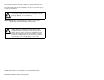
English Step 1. Refer to figure 2.2. Remove the backing from the gasket. Step 1. Align the keypad with the drilled holes in the door and install the keypad to the enclosure. Step 1. Fasten the keypad to the enclosure using the six M6-32 KEPS screws. Tighten the screws in the sequence indicated in figure 2.2. Temporarily torque all screws to 0.3 Nm (2.7 in lb), then re-torque to 0.6 Nm (6.0 in lb). This ensures a good seal between the gasket and the enclosure. ø4,5 [ 0.18] [100] 3.94 7,5 [ 0.30] 70 [ 2.
English 1 2 3 2 3 2 5 6 5 6 1 4 1 4 Final Torque 0.6 N-m (6 in.-lb) Temporary Torque 0.3 N-m (2.7 in-lb) 3 4 No Gap Figure 2.
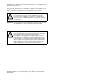
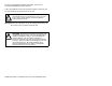
English 2.3 Connecting the Remote Keypad to the Drive ! ATTENTION: Attaching earth ground to the drive control common terminal is recommended to improve noise immunity. In addition, the control common terminal must be grounded if the Remote Keypad is to be connected or disconnected with the drive under power. Failure to observe this precaution could result in severe bodily injury or loss of life. Use the following procedure to connect the Remote Keypad to the drive. Step 1.
English 2.4 Disconnecting the Cable from the Drive and Keypad The 3-meter and 5-meter connector cables have a locking mechanism to ensure that the cable will not be disconnected accidentally. To remove the connector from the drive or the Remote Keypad, pull back on the plastic housing of the cable connector.
English 2-6 SP200 AC Drive Remote Keypad
English CHAPTER 3 Operating the Drive Using the Remote Keypad The following table tells you how to operate the keypad. Table 3.1 – Keypad Operation Desired Action Start the drive1 Stop the drive User Steps Press the green Press the red key to start the drive. key to stop the drive. Jog the drive1 Press and hold down the JOG key to jog the drive. The drive will jog at the frequency selected in P-40 (Internal/Jog Frequency) until the key is released.
English Table 3.1 – Keypad Operation (Continued) Desired Action User Steps View the number of the present display parameter While in display mode, press and release the key once. The present display parameter number will be displayed for 2 seconds. The display will then return to the present parameter value. Increment the display parameter number While in display mode, press the key until the desired parameter is displayed. Following a 2 second delay, the parameter value will be displayed.
English APPENDIX A Technical Specifications Dimensions 34,23 [ 1.35 ] 128,6 [ 5.06] 11,5 [0.45] 168,2 [ 6.62] Ambient Conditions • Operating temperature: 0° C to 50° C (32° F to 122° F) • Storage temperature: -40° C to 85° C (-40° F to 185° F) • Elevation: 1000 meters (3300 ft) maximum without derating. Above 1000 meters, consult your local Reliance Electric sales office.
English Standards and Approvals • UL508C • CSA 22.
English DIF Documentation Improvement Form Use this form to give us your comments concerning this publication or to report an error that you have found. For convenience, you may attach copies of the pages with your comments. After you have completed this form, please return it to: Reliance Electric Technical Documentation 24800 Tungsten Road Cleveland, Ohio 44117 Fax: 216.266.
Français TABLE DES MATIERES Chapitre 1 Généralités sur la console de commande et de programmation à distance ........................... 1-1 1.1 Fonction de la console de commande et de programmation..........................................1-2 1.2 Description de l’affichage................................... 1-4 1.3 Description des LED ..........................................1-4 1.4 Matériel associé ................................................. 1-5 1.5 Publications associées........................
Français II Console de commande et de programmation à distance du variateur de vitesse SP200 CA
Français Liste des Figures Figure 1.1 – Console de commande et de programmation à distance.......................................... 1-1 Figure 1.2 – Fonctions de la console de commande et de programmation à distance................................. 1-2 Figure 2.1 – Gabarit de montage de la console de commande et de programmation à distance ............. 2-2 Figure 2.2 – Montage de la console de commande et de programmation à distance................................. 2-3 Figure 2.
Français IV Console de commande et de programmation à distance du variateur de vitesse SP200 CA
Français CHAPITRE 1 Généralités sur la console de commande et de programmation à distance La console de commande et de programmation à distance peut être utilisée pour modifier les paramètres, afficher les conditions d’utilisation et commander le fonctionnement du variateur. Elle se raccorde au connecteur circulaire mini-DIN du variateur par l’intermédiaire d’un câble de connexion (voir la section 1.4 pour plus de détails). Elle est compatible avec tous les modèles de SP200 (voir la section 1.
Français Le tableau 1.1 indique les références des pièces de la console de commande et de programmation à distance. Tableau 1.1 – Numéros des pièces de la console Description Qté. Console de commande et de programmation à distance 1 Joint 1 42336-046-01 Manuel d’utilisation 1 D2-3431 1.1 Numéro de pièce Fonction de la console de commande et de programmation La figure 1.
Français Tableau 1.2 – Fonctions de la console de commande et de programmation à distance Description 1 La touche PROG (Programmation) fait basculer entre les modes Affichage et Programmation. La diode électroluminescente (LED) PROG (Programmation) s’allume lorsque le variateur est en mode Programmation. 2 En mode Affichage, la touche ENTRÉE permet de faire défiler les paramètres d’affichage. En mode Programmation, cette touche fait basculer entre le numéro et la valeur d’un paramètre.
Français 1.2 Description de l’affichage La console comporte un affichage à quatre caractères (numéroté 9 sur la figure 1.2) qui permet de visualiser les numéros et les valeurs des paramètres. Elle contrôle sa connexion au variateur et affiche en cas de défaillance de la connexion par suite de bruit électrique ou de panne matérielle. En cas de panne du variateur, l’ensemble de l’affichage clignote pour indiquer l’existence de la panne, dont le code apparaît ensuite.
Français 1.4 Matériel associé La console de commande et de programmation à distance se raccorde au variateur de vitesse SP200 CA par l’intermédiaire d’un câble de connexion. Ce câble doit être acheté séparément. Il est possible de choisir entre les numéros de modèles suivants : 1.
Français 1-6 Console de commande et de programmation à distance du variateur de vitesse SP200 CA
CHAPITRE 2 Installation de la console de commande et de programmation à distance Ce chapitre décrit l’installation de la console de commande et de programmation à distance et son raccordement au variateur. 2.1 Préparation de l’installation Sélectionner l’emplacement de montage. Il doit être : 2.
Étape 3. Ebarber les trous et la découpure. Étape 4. Se reporter à la figure 2.2. Décoller la feuille de protection au dos du joint. Étape 5. Aligner la console sur les trous percés dans la porte pour installer la console sur l’armoire. Étape 6. Fixer la console à l’armoire au moyen des six vis KEPS M6-32. Serrer ces vis dans l’ordre indiqué sur la figure 2.2. Serrer provisoirement les vis avec un couple de torsion jusqu’à 0,3 N·m (2,7 lb-po.), puis les resserrer jusqu’à 0,6 N·m (6 lb-po.).
1 2 3 2 3 2 5 6 5 6 1 4 1 4 Couple final 0,6 N·m (6 lb-po.) Couple provisoire 0,3 N·m (2,7 lb-po.) 3 4 Absence d’espace Figure 2.
2.3 Raccordement de la console de commande et de programmation à distance au variateur ! ATTENTION : Il est recommandé de fixer la mise à la terre à la borne Commun du variateur pour améliorer l’immunité contre le bruit, mais il est impératif de le faire si la console de commande et de programmation à distance doit être connectée ou déconnectée alors que le variateur est sous tension. Tout défaut d’observation de ces précautions peut entraîner de graves dommages corporels ou même la mort.
Figure 2.3 – Raccordement de la console de commande et de programmation à distance au variateur 2.4 Débranchement du câble du variateur et de la console Les câbles de connexion de 3 et 5 mètres sont pourvus d’un mécanisme de verrouillage évitant tout débranchement accidentel du câble. Pour débrancher le connecteur du variateur ou de la console de commande et de programmation à distance, tirer sur la coquille en plastique du connecteur de câble.
2-6 Console de commande et de programmation à distance du variateur de vitesse SP200 CA
Français CHAPITRE 3 Utilisation du variateur à l’aide de la console de commande et de programmation à distance Le tableau qui suit décrit le mode d’emploi de la console. Tableau 3.1 – Fonctionnement de la console Résultat recherché Mise en marche du variateur1 Arrêt du variateur Opérations Appuyer sur la touche variateur en marche. verte pour mettre le Appuyer sur la touche variateur.
Français Tableau 3.1 – Fonctionnement de la console (suite) Résultat recherché Opérations Visualisation du numéro du paramètre d’affichage sélectionné Appuyer sur la touche et la relâcher une fois en mode Affichage. Le numéro du paramètre affiché apparaît pendant 2 secondes, puis l’affichage revient à la valeur du paramètre sélectionné. Incrémentation du numéro de paramètre d’affichage Appuyer sur la touche en mode Affichage jusqu’à ce que le paramètre désiré soit affiché.
Français ANNEXE A Spécifications techniques Dimensions 34,23 [1,35] 128,6 [5,06] 11,5 [0,45] 168,2 [6,62] Conditions ambiantes • Température de service : 0 °C à 50 °C (32 °F à 122 °F) • Température de stockage : -40 °C à 85 °C (-40 °F à 185 °F) • Altitude : 1 000 mètres (3 300 pieds) maximum sans déclassement. Au-dessus de 1 000 mètres, consulter le service commercial de Reliance Electric.
Français Normes et agréments • UL508C • ACNOR 22.
Français DIF Formulaire d’amélioration de la documentation Utiliser ce formulaire (DIF) pour nous faire part des observations qu’appelle cette publication ou pour signaler toute erreur relevée. Pour nous faciliter la tâche, joindre une copie de chaque page faisant l’objet de commentaires. Une fois ce formulaire rempli, bien vouloir le renvoyer à : Reliance Electric Technical Documentation 24800 Tungsten Road Cleveland, Ohio 44117 U.S.A. Fax: 216.266.
Deutsch INHALTSVERZEICHNIS Kapitel 1 Die Fernbedienung – Allgemeines........................ 1-1 1.1 Funktionen der Fernbedienung.......................... 1-2 1.2 Beschreibung des Anzeigefelds......................... 1-4 1.3 Beschreibung der Leuchtdioden ........................ 1-4 1.4 Erforderliche Hardware ...................................... 1-5 1.5 Weitere Publikationen ........................................ 1-5 1.6 Kompatibilitât mit früheren FU-Versionen ..........
Deutsch II Frequenzumrichter SP200 – Fernbedienung
Deutsch Abbildungsverzeichnis Abbildung 1.1 – Fernbedienung ..................................................... 1-1 Abbildung 1.2 – Funktionen und Elemente der Fernbedienung ..... 1-2 Abbildung 2.1 – Montageschablone für Fernbedienung................ 2-2 Abbildung 2.2 – Installation der Fernbedienung ............................. 2-3 Abbildung 2.3 – Anschließen der Fernbedienung an den FU........ 2-4 Tabellenverzeichnis Tabelle 1.1 – Einzelteile und Teilenummern ..................................
Deutsch IV Frequenzumrichter SP200 – Fernbedienung
Deutsch KAPITEL 1 Die Fernbedienung – Allgemeines Mit Hilfe der Fernbedienung können Parameterwerte eingestellt, Betriebsbedingungen angezeigt sowie der Betrieb des Frequenzumrichters gesteuert werden. Sie wird über ein Verbindungskabel (Näheres siehe Abschnitt 1.4) mit der runden Mini-DIN-Buchse des FU verbunden und ist mit sämtlichen SP200 FU-Modellen kompatibel (Näheres siehe Abschnitt 1.6). Abbildung 1.
Deutsch Tabelle 1.1 enthält eine Liste der zur Fernbedienung gehörigen Einzelteile. Tabelle 1.1 – Lieferumfang und Bestandteile Beschreibung Anzahl Teilenummer Fernbedienung 1 Dichtung 1 42336-046-01 Handbuch 1 D2-3431 1.1 Funktionen der Fernbedienung In Abbildung 1.2 sind die Tasten, Leuchtdioden und Anzeigefunktionen der Fernbedienung dargestellt. Tabelle 1.2 enthält eine Beschreibung der einzelnen Funktionen und Elemente. In den Abschnitten 1.2 und 1.
Deutsch Tabelle 1.2 – Funktionen und Elemente der Fernbedienung Beschreibung 1 Die „PROGRAM“-Taste schaltet zwischen Anzeige- und Programmodus um. Die Leuchtdiode „PROGRAM“ leuchtet auf, wenn sich der FU im Programmodus befindet. 2 Im Anzeigemodus bewirkt die ENTER-Taste einen Sprung auf den nächsthöheren Anzeigeparameter. Im Programmodus schaltet die ENTER-Taste zwischen der Parameternummer und dem Parameterwert um. 3 Im Anzeigemodus erhöht die AUFWÄRTS-Taste den lokalen Drehzahl-Sollwert.
Deutsch 1.2 Beschreibung des Anzeigefelds Die Fernbedienung verfügt über ein vierstelliges Anzeigefeld (Ziffer 9 in Abbildung 1.2), das die Parameternummern und -werte darstellt. Die Fernbedienung überprüft stets die Verbindung mit dem Frequenzumrichter und zeigt vier Striche an, wenn die Verbindung aufgrund eines Hardwarefehlers gestört ist. Wenn der Frequenzumrichter ausfällt, blinkt die Anzeige und zeigt den Fehlercode an.
Deutsch 1.4 Erforderliche Hardware Die Fernbedienung wird über ein Verbindungskabel mit dem Frequenzumrichter SP200 verbunden. Dieses ist gesondert zu erwerben. Die folgenden Modelle sind verfügbar: 1.5 • M/N S20-KC1 – Verbindungskabel, 1 m Länge • M/N S20-KC3 – Verbindungskabel, 3 m Länge • M/N S20-KC5 – Verbindungskabel, 5 m Länge Weitere Publikationen Der Benutzer muß mit allen das System beschreibenden Anleitungen und Handbüchern vertraut sein. Dazu zählen unter anderem: 1.
Deutsch 1-6 Frequenzumrichter SP200 – Fernbedienung
Deutsch KAPITEL 2 Montage der Fernbedienung Dieses Kapitel beschreibt die Montage der Fernbedienung und deren Anschluß an den FU. 2.1 Planung der Montage Bei der Wahl eines geeigneten Montageortes ist auf folgende Bedingungen zu achten: 2.
Deutsch 5. Fernbedienung auf die gebohrten Löcher in der Tür ausrichten und die Fernbedienung auf das Gehäuse aufsetzen. 6. Fernbedienung mit Hilfe der 6 M6-32 KEPS-Schrauben am Gehäuse anbringen. Die Schrauben sind in der in Abb. 2.2 dargestellten Reihenfolge anzuziehen. Schrauben zunächst mit einem Drehmoment von 0,3 Nm fixieren, danach mit 0,6 Nm festziehen. Dies garantiert eine gut schließende Verbindung zwischen Dichtung und Gehäuse. ø4,5 100 7,5 70 140 135 90 5 Abmessungen in mm Abbildung 2.
Deutsch 1 2 3 2 3 2 5 6 5 6 1 4 1 4 Danach mit 0,6 Nm festziehen Zunächst mit 0,3 Nm fixieren 3 4 Kein Spalt! Abbildung 2.
Deutsch 2.3 Anschließen der Fernbedienung an den FU ! ACHTUNG: Zur Verbesserung der Störfestigkeit wird das Anschließen einer Erdung an den Steuer-Klemmenblock des FUs empfohlen. Darüber hinaus ist dieser Klemmenblock zu erden, wenn die Fernbedienung ein- oder ausgesteckt werden soll, während am FU Strom anliegt. Die Nichtein-haltung dieser Sicherheitsmaßnahme kann schwere oder tödliche Körperverletzungen zur Folge haben. Das Anschließen der Fernbedienung ist wie folgt vorzunehmen: 1.
Deutsch 2.4 Abziehen des Verbindungskabels von FU oder Fernbedienung Die 3 und 5 Meter langen Verbindungskabel verfügen über eine Schnappvorrichtung, mit der ein unbeabsichtigtes Lösen des Kabels vermieden werden kann. Zum Lösen der Kabel mit dieser Einrichtung ist das Plastikgehäuse des Kabelsteckers nach hinten abzuziehen.
Deutsch 2-6 Frequenzumrichter SP200 – Fernbedienung
Deutsch KAPITEL 3 Betrieb des FUs mit Fernbedienung Die folgende Tabelle enthält Anweisungen zum Betrieb der Fernbedienung: Tabelle 3.1 – Betrieb der Fernbedienung Gewünschter Arbeitsschritt Starten des FU1 Anhalten des FU Vorgangsweise Zum Starten des FU die grüne Taste drücken. Zum Anhalten des FU die rote Taste drücken. Stufenweises Erhöhen durch Tastendruck1 Zum stufenweisen Erhöhen der Frequenz die JOGTaste (Tippbetrieb) gedrückt halten.
Deutsch Tabelle 3.1 – Betrieb der Fernbedienung Gewünschter Arbeitsschritt Vorgangsweise Nummer des aktuellen Parameters anzeigen (Anzeigemodus) Zum Anzeigen der Nummer des aktuellen Parameters im Anzeigemodus die Taste einmal drücken. Die Nummer wird dann 2 Sekunden lang angezeigt. Danach wird wieder der Wert des aktuellen Parameters angezeigt.
Deutsch ANHANG A Technische Daten Abmessungen 34,23 128,6 11,5 168,2 Umgebungsbedingungen • Betriebstemperatur: 0 °C bis 50 °C • Lagertemperatur: -40 °C bis 85 °C • Aufstellungshöhe: 1000 m oder weniger ohne Leistungsreduktion. Bei Aufstellungshöhen über 1000 m bitte das nächstgelegene Reliance Electric Vertriebsbüro kontaktieren. • Relative Luftfeuchtigkeit: 0 bis 95% nichtkondensierend Ein-/Ausgangsspannungen • Eingangsspannung: 5 V= (vom FU versorgt) • Eingangsstrom: max.
Deutsch Eingehaltene Normen und Richtlinien • UL508C • CSA 22.
Deutsch DIF Documentation Improvement Form (Anregungen zur Verbesserung der Dokumentation) Mit diesem Formular können Anmerkungen über diese Publikation abgegeben oder etwaige entdeckte Fehler gemeldet werden. Kopien der betreffenden Seiten sind zur Erleichterung der Bearbeitung dem Formular beizulegen.
Italiano INDICE Capitolo 1 Informazioni sul tastierino remoto...................... 1-1 1.1 Funzioni del tastierino numerico.......................1-2 1.2 Descrizione del display..................................... 1-4 1.3 Descrizione dei LED ......................................... 1-4 1.4 Hardware correlati ............................................ 1-5 1.5 Documentazioni correlate................................. 1-5 1.6 Compatibilità con versioni precedenti dell’inverter ..........................
Italiano II Tastierino Remoto per L’inverter C.A.
Italiano Elenco delle Figure Figura 1.1 – Tastierino remoto ....................................................... 1-1 Figura 1.2 – Funzioni del tastierino ................................................ 1-2 Figura 2.1 – Sagoma dell’installazione del tastierino remoto ........ 2-2 Figura 2.2 – Installazione del tastierino remoto.............................. 2-3 Figura 2.3 – Collegamento del tastierino remoto all’inverter ......... 2-4 Elenco delle Tabelle Tabella 1.1 – Contenuto e numero di catalogo...
Italiano IV Tastierino Remoto per L’inverter C.A.
Italiano CAPITOLO 1 Informazioni sul tastierino remoto Il tastierino remoto può essere usato per cambiare i valori dei parametri, visualizzare le condizioni operative e controllare il funzionamento dell’inverter. Il tastierino remoto si collega al connettore circolare mini-DIN dell’inverter tramite un cavo connettore (per ulteriori informazioni, vedere la sezione 1.4). Il tastierino è compatibile con tutti i modelli dell’inverter SP200 (per ulteriori informazioni, vedere la sezione 1.6). La figura 1.
Italiano La tabella 1.1 riporta l’elenco delle parti del tastierino remoto. Tabella 1.1 – Contenuto e numero di catalogo Descrizione Q.tà Numero di catalogo Tastierino remoto 1 Guarnizione 1 42336-046-01 Manuale delle istruzioni 1 D2-3431 1.1 Funzioni del tastierino numerico La figura 1.2 identifica i tasti del tastierino remoto, gli indicatori LED e le funzioni del display. La tabella 1.2 descrive le funzioni del tastierino remoto. Le sezioni 1.2 e 1.
Italiano Tabella 1.2 – Funzioni del tastierino Descrizione 1 Il tasto PROGRAM alterna le modalità di visualizzazione e programma. Il LED PROGRAM si accende quando l’inverter è in modalità programma. 2 In modalità visualizzazione, il tasto INVIO scorre i parametri di visualizzazione. In modalità programma, questo tasto alterna il numero ed il valore del parametro. 3 In modalità visualizzazione, il tasto Freccia in su aumenta il riferimento della velocità locale.
Italiano 1.2 Descrizione del display Il tastierino dispone un display a quattro caratteri (indicati con il numero 9 nella figura 1.2), usati per visualizzare i numeri ed i valori dei parametri. Il tastierino controlla il proprio collegamento all’inverter e visualizza se il collegamento si interrompe a causa di un guasto meccanico o di un disturbo elettrico. Se l’inverter si guasta, l’intero display lampeggia per indicare la presenza di un guasto e si visualizza il codice corrispondente.
Italiano 1.4 Hardware correlati Il tastierino remoto si collega all’inverter SP200 tramite un cavo connettore. Il cavo deve essere acquistato a parte. Sono disponibili i seguenti modelli di cavi: 1.5 • M/N S0-KC1 – cavo connettore lungo 1 metro • M/N S20-KC3 – cavo connettore lungo 3 metri • M/N S20-KC5 – cavo connettore lungo 5 metri Documentazioni correlate È necessario che l’utente conosca bene tutti i manuali delle istruzioni relative al proprio sistema.
Italiano 1-6 Tastierino Remoto per L’inverter C.A.
Italiano CAPITOLO 2 Installazione del tastierino remoto Questo capitolo spiega la procedura di installazione e di collegamento del tastierino remoto all’inverter. 2.1 Pianificazione dell’installazione Selezionare il punto di installazione. Questo deve essere: 2.
Italiano Passo 6. Fissare il tastierino alla custodia usando le sei viti M6-32 KEPS. Avvitare le viti nell’ordine indicato nella figura 2.2. Serrare temporaneamente tutte le viti a 0,3 Nm (2,7 in-lb), quindi a 0,6 Nm (6 in-lb). Così facendo, si assicura una buona tenuta fra la guarnizione e la custodia. ø4,5 [0,18] 100 [3,94] 7,5 [0,30] 70 [2,76] 140 [5,51] 135 [5,32] 90 [3,54] 5 [0,20] dimensioni = mm [poll.] Figura 2.
Italiano 1 2 3 2 3 2 5 6 5 6 1 4 1 4 Torsione temporanea 0,3 Nm (2,7 in-lb) Torsione finale 0,6 Nm (6 in-lb) 3 4 Nessuno spazio Figura 2.
Italiano 2.3 Collegamento del tastierino remoto all’inverter ! ATTENZIONE:per aumentare l’immunità ai disturbi, si raccomanda di collegare a massa il terminale comune di controllo dell’inverter. Il terminale comune di controllo deve inoltre essere collegato a massa se il tastierino remoto viene collegato o scollegato con l’inverter alimentato. L’inosservanza di questa precauzione può causare gravi infortuni a persone o morte.
Italiano 2.4 Scollegamento del cavo dall’inverter e dal tastierino I cavi connettori da 3 e da 5 metri dispongono di un meccanismo di bloccaggio che impedisce lo scollegamento accidentale dei cavi. Per rimuovere il connettore dall’inverter o dal tastierino remoto, tirare indietro l’alloggiamento di plastica del connettore del cavo.
Italiano 2-6 Tastierino Remoto per L’inverter C.A.
Italiano CAPITOLO 3 Uso dell’inverter per mezzo del tastierino remoto La tabella seguente spiega come usare il tastierino. Tabella 3.1 – Uso del tastierino Azione desiderata Interventi dell’utente Avvio dell’inverter1 Per avviare l’inverter, premere il tasto verde Arresto dell’inverter Per arrestare l’inverter, premere il tasto rosso . . Marcia a impulsi dell’inverter1 Per far marciare l’inverter a impulsi, tenere premuto il tasto JOG.
Italiano Tabella 3.1 – Uso del tastierino (Continuazione) Azione desiderata Interventi dell’utente Vedere il numero del parametro corrente sul display In modalità visualizzazione, premere e rilasciare il tasto una sola volta. Il numero del parametro corrente sul display viene visualizzato per 2 secondi. Il display torna poi al valore del parametro corrente. Aumentare il numero del parametro sul display In modalità visualizzazione, premere il tasto fino a quando non appare il parametro desiderato.
Italiano APPENDICE A Specifiche tecniche Dimensioni 34,23 [1,35] 128,6 [5,06] 11,5 [0,45] 168,2 [6,62] Condizioni ambientali • Temperatura di esercizio: da 0 a 50° C • Temperatura di immagazzinamento: da -40° C a 85° C • Altezza: 1000 metri massimo senza riduzione. Oltre i 1000 metri, informarsi presso l’ufficio vendite della Reliance Electric.
Italiano Potenza nominale ingresso/uscita • Tensione in ingresso: 5V C.C. (fornita dall’inverter) • Corrente in ingresso: 80 mA (massimo, fornita dall’inverter) Standard e omologazioni • UL508C • CSA 22.2 • EN50178, EN60204-1 per Direttiva sulla bassa tensione • EN50081-1, EN50082-2, parti di EN61800-3 per EMC • IP52 (NEMA tipo 12, UL tipo 4X solo per uso all’interno) A-2 Tastierino Remoto per L’inverter C.A.
Italiano DIF Commenti sulla documentazione Usate questo modulo per fornirci i vostri commenti su questa documentazione (DIF) o per comunicarci eventuali errori trovati. Per comodità, potrete allegare ai vostri commenti copie delle pagine interessate. Dopo aver compilato questo modulo, speditelo a: Reliance Electric Technical Documentation 24800 Tungsten Road Cleveland, Ohio 44117 U.S.A. Fax: 216.266.
Português ÍNDICE Capítulo 1 Informações sobre o teclado remoto ................... 1-1 1.1 Recursos do teclado ..........................................1-2 1.2 Descrição do Teclado ........................................ 1-4 1.3 Descrições dos LEDs......................................... 1-4 1.4 Hardware Relacionado ...................................... 1-5 1.5 Publicações........................................................ 1-5 1.6 Compatibilidade com as versões anteriores do inversor ............
Português II Teclado Remoto do Inversor CA SP200
Português Lista das Figuras Figura 1.1 – Teclado Remoto1-1 Figura 1.2 – Recursos do Teclado1-2 Figura 2.1 – Gabarito de montagem do teclado remoto 2-2 Figura 2.2 – Montagem do teclado remoto2-3 Figura 2.3 – Conexão to teclado remoto ao inversor 2-4 Lista das Tabelas Tabela 1.1 – Conteúdos do Número do Modelo1-2 Tabela 1.2 – Recursos do Teclado1-3 Tabela 1.3 – Funções dos LEDs1-4 Tabela 3.
Português IV Teclado Remoto do Inversor CA SP200
Português CAPÍTULO 1 Informações sobre o teclado remoto O teclado remoto pode ser utilizado para mudar valores de parâmetros, mostrar condições de operação e a operação do inversor de comando. Ele conecta ao conector circular mini-DIN do inversor por um cabo conector (veja a seção 1.4 para maiores informações). Ele é compatível com todos os inversores SP200 (veja a seção 1.6 para maiores informações). A figura 1.1 mostra o teclado remoto. Consulte o Apêndice A quanto às suas dimensões. Figura 1.
Português A Tabela 1.1 fornece uma lista de peças para o teclado remoto. Tabela 1.1 – Conteúdos do Número do Modelo Descrição Qtd. Número da Peça Teclado remoto 1 Gaxeta 1 42336-046-01 Manual de Instrução 1 D2-3431 1.1 Recursos do teclado A figura 1.2 identifica as teclas do teclado remoto, LEDs e os recursos da tela. A tabela 1.2 descreve esses recursos do teclado remoto. As seções 1.2 e 1.3 descrevem o mostrador do teclado e os LEDs (denominados 9 e 10 na figura 1.2).
Português Tabela 1.2 – Recursos do Teclado Descrição 1 A tecla PROGRAM comuta entre os modos de exibição e programação. O PROGRAM LED (LED DE PROGRAMAÇÃO) acende quando o inversor está no modo de programação. 2 No modo de exibição, a tecla ENTER rola pelos parâmetros de exibição. No modo de programação, esta tecla comuta entre o número e o valor do parâmetro. 3 No modo de exibição, a tecla SETA PARA CIMA aumenta a referência de velocidade local.
Português 1.2 Descrição do Teclado O teclado possui um mostrador de quatro caracteres (denominado 9 na figura 1.2), o qual é utilizado para mostrar os números e valores dos parâmetros. O teclado monitora sua conexão ao inversor e exibirá se a conexão falhar devido a ruído elétrico ou uma falha de hardware. Se o inversor falhar, a tela inteira piscará para indicar a falha, e o código da falha será exibida.
Português 1.4 Hardware Relacionado O teclado remoto conecta ao Inversor CA SP200 através de um cabo conector. Este cabo deve ser comprado separadamente. Os seguintes números de modelos estão disponíveis: 1.5 • M/N S20-KC1 – Cabo conector de 1 metro • M/N S20-KC3 – Cabo conector de 3 metros • M/N S20-KC5 – Cabo conector de 5 metros Outros Manuais Você deve se familiarizar com todos os manuais de instrução que descrevem o seu sistema, incluindo, mas não limitado a: 1.
Português 1-6 Teclado Remoto do Inversor CA SP200
Português CAPÍTULO 2 Instalação do Teclado Remoto Este capítulo descreve como instalar o teclado remoto e conectá-lo ao inversor. 2.1 Planejamento da Instalação Selecione o local de montagem. O local de montagem deve ser: 2.
Português Passo 5. Alinhe o teclado com os buracos perfurados na porta e instale o teclado à cobertura. Passo 6. Prenda o teclado à cobertura usando seis parafusos M6-32 KEPS. Aperte os parafusos de acordo com a seqüência indicada na figura 2.2. Aplique um torque (pre-aperto) de 0,3 Nm (2,7 libras-pol.), e depois um outro torque de 0,6 Nm (6,0 libras-pol.). Isso assegurará uma boa vedação entre a gaxeta e a cobertura.
Português 1 2 3 2 3 2 5 6 5 6 1 4 1 4 Pre-apertar com torque de 0,3 Nm (2,7 libras-pol.) Torque final de 0,6 Nm (6,0 libras-pol.) 3 4 Sem afastamento (folga) Figura 2.
Português 2.3 Conexão to teclado remoto ao inversor ! ATENÇÃO: Recomenda-se a ligação do fio terra ao terminal comum de controle do inversor para melhorar a imunização de ruídos. Além disso, o terminal comum de controle deve ser aterrado se o teclado remoto deve ser conectado ou desconectado quando o inversor estiver energizado (alimentado por energia). Se esta precaução não for observada pode resultar em lesão corporal grave ou morte.
Português 2.4 Desconexão do cabo do inversor e do teclado Os cabos conectores de 3 e 5 metros possuem um mecanismo de travamento para assegurar que o cabo não desconecte acidentalmente. Para remover o cabo do inversor ou do teclado rápido, puxe o encaixe plástico do conector do cabo para trás.
Português 2-6 Teclado Remoto do Inversor CA SP200
Português CAPÍTULO 3 Operação do inversor utilizando o teclado remoto A tabela a seguir descreve como operar o teclado. Tabela 3.1 – Operação do teclado Ação desejada Dar partida no inversor1 Parar o inversor Passos do usuário Pressione a tecla inversor. verde para dar partida no Pressione a tecle inversor. vermelha para parar o Marcha por impulso (JOG)1 Pressione e prenda a tecla JOG (IMPULSO) para ressaltar o inversor.
Português Tabela 3.1 – Operação do teclado (Continuação) Ação desejada Passos do usuário Visualizar o número do parâmetro de exibição do momento No modo de exibição, pressione e solte a tecla uma vez. O número do parâmetro de exibição do momento será exibido por 2 segundos. Em seguida, a tela volta a exibir o valor do parâmetro de exibição do momento. Aumentar o número do parâmetro de exibição No modo de exibição, pressione a tecla até que o parâmetro desejado apareça.
Português APÊNDICE A Especificações Técnicas Dimensões 34,23 [1,35] 128,6 [5,06] 11,5 [0,45] 168,2 [6,62] Condições ambientais • Temperatura de operação: 0 a 50 °C • Temperatura de armazenamento: -40 a 85 °C • Altitude: Máximo de 1000 metros sem redução. Consulte o escritório de vendas da Reliance Electric para alturas acima de 1000 metros.
Português Padrões e aprovações • UL508C • CSA 22.
Português DIF Formulário de Aperfeiçoamento da Documentação Use este formulário (DIF) para enviar seus comentários referentes a esta publicação ou para relatar algum erro que você tenha encontrado. Para a sua conveniência, você pode anexar as cópias das páginas com os seus comentários. Após preencher este formulário, remeta-o para: Reliance Electric Technical Documentation 24800 Tungsten Road Cleveland, Ohio 44117 EUA Fax: 216.266.
Español ÍNDICE Capítulo 1 Acerca del teclado de control remoto .................. 1-1 1.1 Características del teclado................................. 1-2 1.2 Descripción de la pantalla.................................. 1-4 1.3 Descripciones de las luces indicadoras ............. 1-4 1.4 Equipo relacionado ............................................ 1-5 1.5 Publicaciones relacionadas ............................... 1-5 1.6 Compatibilidad con versiones anteriores del variador .............................
Español II Teclado de control remoto del variador SP200 de CA
Español Lista de Figuras Figura 1.1 – Teclado de control remoto.......................................... 1-1 Figura 1.2 – Características del teclado ......................................... 1-2 Figura 2.1 – Plantilla de montaje del teclado de control remoto.... 2-2 Figura 2.2 – Montaje del teclado de control remoto ....................... 2-3 Figura 2.3 – Conexión del teclado de control remoto al variador de velocidad ............................................ 2-4 Lista de Tablas Tabla 1.
Español IV Teclado de control remoto del variador SP200 de CA
Español CAPÍTULO 1 Acerca del teclado de control remoto El teclado de control remoto puede utilizarse para cambiar parámetros y valores, visualizar condiciones de funcionamiento y controlar el funcionamiento del variador de velocidad. El teclado se conecta al conector mini-DIN ubicado en el variador, mediante un cable conector (Consulte la sección 1.4 para mayor información sobre este punto). El teclado es compatible con todos los modelos de variadores de velocidad de la serie SP200 (Consulte la sección 1.
Español La tabla 1.1 proporciona una lista de piezas de repuesto para el teclado de control remoto. Tabla 1.1 – Índice del número de modelo Descripción Cantidad Teclado de control remoto 1 Marco de montaje 1 42336-046-01 Manual de instrucciones 1 D2-3431 1.1 Número de referencia Características del teclado En la Figura 1.2 se muestran las teclas del teclado de control remoto, las luces indicadoras (LED) y las características de la pantalla. La tabla 1.
Español Tabla 1.2 – Características del teclado Descripción 1 Por medio de la tecla PROG se puede alternar entre el modo de visualización y programación. La luz indicadora PROGRAM se enciende cuando el variador de velocidad está en el modo de programación. 2 En el modo de visualización, la tecla ENTER muestra los distintos parámetros. En el modo de programación, esta tecla alterna entre los números y los valores de parámetro.
Español 1.2 Descripción de la pantalla El teclado cuenta con una pantalla de cuatro caracteres (designada con el número 9 en la figura 1.2), la cual se utiliza para mostrar números y valores de parámetros. El teclado visualiza su conexión al variador de velocidad y mostrará si la conexión falla debido a interferencia eléctrica o a un defecto del equipo.
Español 1.4 Equipo relacionado El teclado de control remoto se conecta al Variador de velocidad SP200 de corriente alterna por medio de un cable conector. Este cable puede adquirirse por separado. A continuación se detalla una lista de los modelos disponibles: 1.
Español 1-6 Teclado de control remoto del variador SP200 de CA
Español CAPÍTULO 2 Instalación del teclado de control remoto En este capítulo se explica cómo instalar el teclado de control remoto y cómo conectarlo al variador de velocidad. 2.1 Planificación de la instalación Seleccione la ubicación donde desea montar el teclado. Ésta deberá: 2.
Español Paso 4. Consulte la figura 2.2. Retire el respaldo del marco de montaje. Paso 5. Alinee el teclado de control remoto con los orificios perforados en la puerta e instale el teclado en el armario. Paso 6. Fije el teclado al armario valiéndose de los seis tornillos M6-32 KEPS. Apriete los tornillos de acuerdo con la secuencia indicada en la figura 2.2. Ajuste los tornillos momentáneamente a un par de apriete de 0,3 N·m (2,7 pulg./lb.). Enseguida vuelva a apretar a 0,6 N·m (6,0 pulg./lb.).
Español 1 2 3 2 3 2 5 6 5 6 1 4 1 4 Par de apriete provisional 0,3 N·m (2,7 pulg./lb) Par de apriete final 0,6 N·m (6 pulg./lb) 3 4 Sin separación Figura 2.
Español 2.3 Conexión del teclado de control remoto al variador de velocidad ! ATENCIÓN: Se recomienda conectar a tierra el terminal común de control del variador de velocidad, a fin de mejorar la inmunidad a las interferencias. Asimismo, el terminal común deberá estar conectado a tierra si el teclado de control ha de conectarse o desconectarse cuando el variador esté conectado a la línea de alimentación. De no observarse esta advertencia podrían sufrirse graves lesiones o incluso la muerte.
Español 2.4 Desconexión del cable del variador de velocidad y el teclado de control Los cables conectores de 3 y 5 metros tienen un mecanismo de sujeción para evitar que el cable se desconecte accidental-mente. Para retirar el conector del variador o del teclado de control remoto, tire hacia atrás de la envolvente de plástico del cable conector.
Español 2-6 Teclado de control remoto del variador SP200 de CA
Español CAPÍTULO 3 Funcionamiento del variador de velocidad mediante el teclado de control remoto La siguiente tabla le indica cómo manejar el teclado de control remoto. Tabla 3.1 – Operación del teclado de control remoto Objetivo Arrancar el variador1 Detener el variador Pasos que debe seguir el usuario Oprimir la tecla velocidad. para arrancar el variador de Oprimir la tecla velocidad.
Español Tabla 3.1 – Operación del teclado de control remoto (Continuación) Objetivo Pasos que debe seguir el usuario Visualizar el número del parámetro actual en el modo de visualización En el modo de visualización, oprimir y soltar la tecla . Enseguida aparecerá el número del parámetro actual aparecerá y permanecerá en la pantalla durante 2 segundos. La pantalla regresará al valor del parámetro mostrado.
Español APÉNDICE A Especificaciones técnicas Dimensiones 34,23 [1,35] 128,6 [5,06] 11,5 [0,45] 168,2 [6,62] Condiciones ambientales • Temperatura de trabajo: 0 °C a 50 °C (32 °F a 122 °F) • Temperatura de almacenamiento: -40 °C a 85 °C (-40 °F a 185 °F) • Elevación: 1000 metros (3300 pies) máximo sin reducción de la capacidad normal. En ubicaciones con altitudes mayores de 1000 metros, consulte con la oficina local de ventas de Reliance Electric.
Español Capacidades nominales de entrada/salida • Tensión de entrada: 5 V CC (suministrada por el variador) • Corriente de entrada: 80 mA (máxima, suministrada por el variador) Aprobaciones y cumplimiento de estándares • UL508C • CSA 22.
U.S. Drives Technical Support Tel: (1) 262.512.8176, Fax: (1) 262.512.2222, Email: support@drives.ra.rockwell.com, Online: www.ab.com/support/abdrives Publication D2-3431– March 1999 Copyright © 1999 Rockwell Automation, Inc. All Rights Reserved.