
Manual


Identify Your Drive
1-1
CHAPTER 1
Identify Your Drive
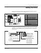
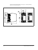
This user’s manual describes the functionality of SP200 drives rated from 0.5 HP to
2 HP. Figure 1.1 shows the location of components.
Figure 1.1 – SP200 AC Drive
SP200 drives are identified by model number. This number appears on the shipping
label and on the unit’s nameplate. Figure 1.2 shows the format of this number and
what it indicates.
Figure 1.2 – Model Number Structure
Item Description
1 Nameplate
2 Status LED
3 Control Signal Terminal Block
4 Motor Output Terminal Block
5Fan
6 Finger Guard (2)
7 Blank Faceplate (Standard)
8 Local Keypad (Optional)
9 AC Input Power Terminal Block
10 DIN Rail Latch
1
2
3
4
5
7
9
6
8
6
10
Enclosure Type
0 = Protected chassis (IP20)
(Reserved - not used)
(Reserved - not used)
(Reserved - not used)
S20
4 0 3P5 A1 0
-
SP200
Voltage
Input
Output
2 = 200-240 V, 3-phase; 230 V, 3-phase
4 = 380-480 V, 3-phase; 460 V, 3-phase
X = Selectable:
Y = 200-240 V, 1-phase; 230 V, 3-phase
100-120 V, 1-phase; 230 V, 3-phase
or
200-240 V, 1-phase; 230 V, 3-phase
Model (Control Type)
A1 = Single Channel Analog
B1 = Preset Speed
C1 = Dual Channel Analog
Output Current (Horsepower)
1P3 = 1.3 A (0.5 HP)
2P0 = 2.0 A (1.0 HP)
2P3 = 2.3 A (0.5 HP)
3P5 = 3.5 A (2.0 HP)
4P2 = 4.2 A (1.0 HP)
6P0 = 6.0 A (1.5 HP)
7P0 = 7.0 A (2.0 HP)
0 0