
Manual


7-4
Installing and Operating the SP200 AC Drive
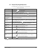
7.1.2 Digital Input/Output Control Parameters (Group 1)
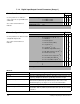
P-10 Start Control Model
A B C
Use this parameter to define the
source of the run, stop, and direction
commands.
See section 9.2 for fault reset
methods.
Parameter Range: 1 = Keypad control
2 = 2-Wire control
3 = 3-Wire control
X
X
X
X
X
X
X
X
X
Default Setting: 2 X X X
Running Access: RO
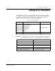
P-11 Configurable Input Model
A B C
Use this parameter to define how the
configurable input works.
See section 9.2 for fault reset
methods.
Parameter Range:
0 = Function Loss (P-10
≠
3)
X
1 = Disabled X
1 = Preset Speed X
1 = Reverse Run (2-wire) X
2 = Jog (P-10
≠
1)
X X
2 = Jog (P-10
≠
1 or 3)
X
3 = Alternate Speed.Reference X X
3 = Alt. Spd. Reference (P-10
≠
3)
X
4 = N.C. Coast to stop X X
4 = N.C. Coast to stop (P-10
≠
3)
X
5 = Secondary Accel/Decel X X
5 = Sec. Accel/Decel (P-10
≠
3)
X
Default Setting: 2 X
1 X
0 X
Running Access: RO
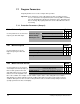
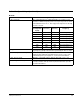
Model A:
When P-11 is set to: Then the configurable input works as follows:
1 (Disabled) The configurable input not used.
2 (Jog) When the configurable input is ON, the drive will jog at the Internal / Jog
Frequency (P-40) in the direction specified by the Reverse input.
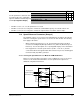
3 (Alternate Speed Reference) When the configurable input is ON, the drive will use the value of
parameter P-21 (Alternate Speed Reference) as the source of the
command frequency. See figure 7.1 or 7.2 for more information
4 (N.C. Coast to Stop) When the configurable input is OFF, the drive will coast to stop.
5 (Secondary Accel/Decel) When the configurable input is ON, the drive will use parameters P-32
(Acceleration Time 2) and P-33 (Deceleration Time 2) for the accel and
decel times.