Installing and Operating the SP200 AC Drive Model A - Single Channel Analog Model B - Preset Speed Model C - Dual Channel Analog Instruction Manual D2-3408
The information in this manual is subject to change without notice. Throughout this manual, the following notes are used to alert you to safety considerations: ! ATTENTION: Identifies information about practices or circumstances that can lead to personal injury or death, property damage, or economic loss. Important: Identifies information that is critical for successful application and understanding of the product.
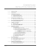
CONTENTS AND INSTALLATION CHECKLIST ❏ Chapter 1 Identify Your Drive.................................................................................................. 1-1 ❏ Chapter 2 Install the Drive ....................................................................................................... 2-1 ❏ Chapter 3 Install External Components ................................................................................. 3-1 3.1 Install Branch Circuit Protection ........................................
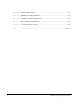
Appendix A Technical Specifications........................................................................................... A-1 Appendix B Alphabetical Listing of Parameters........................................................................... B-1 Appendix C Compliance with EU Requirements ......................................................................... C-1 Appendix D Motor Cable Recommendations...............................................................................
List of Figures Figure 1.1 – SP200 AC Drive ................................................................................... 1-1 Figure 1.2 – Model Number Structure ...................................................................... 1-1 Figure 2.1 – Access Clearances and Installation Guidelines.................................... 2-1 Figure 2.2 – SP200 Drive Mounting Dimensions...................................................... 2-2 Figure 4.1 – AC Input Power Connections ...........................
List of Tables Table 3.1 – Required AC Branch Circuit Protection..................................................3-1 Table 6.1 – Run LED.................................................................................................6-2 Table 6.2 – Program LED .........................................................................................6-2 Table 6.3 – Keypad Operation ..................................................................................6-3 Table 7.1 – Parameter Organization .......
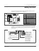
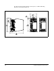
CHAPTER 1 Identify Your Drive This user’s manual describes the functionality of SP200 drives rated from 0.5 HP to 2 HP. Figure 1.1 shows the location of components. 10 9 6 1 7 8 2 3 6 4 5 Item 1 2 3 4 5 6 7 8 9 10 Description Nameplate Status LED Control Signal Terminal Block Motor Output Terminal Block Fan Finger Guard (2) Blank Faceplate (Standard) Local Keypad (Optional) AC Input Power Terminal Block DIN Rail Latch Figure 1.1 – SP200 AC Drive SP200 drives are identified by model number.
1-2 Installing and Operating the SP200 AC Drive
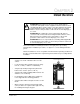
CHAPTER 2 Install the Drive ! ATTENTION: Only qualified electrical personnel, familiar with the construction and operation of this equipment and the hazards involved, should install, adjust, operate, and/or service this equipment. Read and understand this instruction manual in its entirety before proceeding. Failure to observe this precaution could result in severe bodily injury or loss of life. ATTENTION: This equipment is at line voltage when AC power is connected.
The drive must be mounted vertically to a wall, a panel, or a DIN rail. Mounting dimensions are provided in figure 2.2. Figure 2.
CHAPTER 3 Install External Components Install external components using the guidelines in the following sections. Each installation requires either: • an AC input disconnect and input fusing, or • a circuit breaker. 3.1 Install Branch Circuit Protection ! ATTENTION: Many local and national electrical codes require that upstream branch protection be provided to protect input power wiring. The input fuse and circuit breaker ratings listed in table 3.
3.2 Install an AC Input Disconnect ! ATTENTION: Many local and national electrical codes require that an input disconnect be provided in the incoming power lines. Failure to observe this precaution could result in severe bodily injury or loss of life. A user-supplied AC input disconnect must be provided in the incoming power lines in accordance with local and national electrical code guidelines. 3.
CHAPTER 4 Wire Input Power and Output Power ! ATTENTION: This equipment is at line voltage when AC power is connected. Disconnect and lockout all ungrounded conductors of the AC power line before working on the unit. Failure to observe this precaution could result in severe bodily injury or loss of life. ATTENTION: The user is responsible for conforming with all local and national codes applicable to the grounding of this equipment.
4.1 Wire AC Power to the Drive and Motor Use the following procedure to wire power to the drive and motor. Step 1. Remove the finger guards by inserting a screwdriver in the slot at the front of each guard and pushing gently. Step 2. For 115 VAC input power only, remove the protective label from the 115 VAC terminal. Step 3. Connect the incoming AC line to the appropriate input power terminals as shown in figure 4.1. Step 4. Connect a ground wire to the drive’s input grounding screw (labeled PE ).
CHAPTER 5 Wire the Control Signal Terminal Block ! ATTENTION: If 2-wire control is selected, the drive will immediately run when powered up in the presence of a forward or reverse run command. Failure to observe this precaution could result in severe bodily injury or loss of life. The following sections describe how to wire the control signal terminal block. (Refer to figure 1.1 for the location of the terminal block). Refer to figure 5.2 (Model A, Single Channel Analog), 5.
Figure 5.2 – Model A Control Signal Terminal Block Wiring Figure 5.3 – Model B Control Signal Terminal Block Wiring Figure 5.
5.1 Install an Emergency Stop ! ATTENTION: The user must provide an external, hardwired emergency stop circuit outside of the SP200 drive circuitry. This circuit must disable the system in case of improper operation. Uncontrolled machine operation may result if this procedure is not followed. Failure to observe this precaution could result in severe bodily injury or loss of life.
5-4 Installing and Operating the SP200 AC Drive
CHAPTER 6 Using the Local Keypad The optional keypad can be used to change parameter values, display operating conditions, and command drive operation. Figure 6.1 shows the SP200 drive keypad and identifies the keypad keys. 1 In display mode, the UP ARROW key increments the local speed reference. In program mode, this key increments the parameter number or parameter value. 2 The PROGRAM key toggles between display and program modes. The PROGRAM LED (5) turns on when the drive is in program mode.
The following sections describe the four-character display, the Run and Program LEDs, and step-by-step operation of the keypad. 6.1 Display Description The keypad has a four-character display which is used to show parameter numbers and parameter values. The keypad monitors its connection to the drive and will display if this connection fails due to electrical noise or a hardware failure.
6.3 Step-by-Step Keypad Operation The following table provides detailed steps for keypad operation. Table 6.3 – Keypad Operation Desired Action Start the unit1 User Steps Press the green key to start the drive. Stop the unit Press the red key to stop the drive.
6-4 Installing and Operating the SP200 AC Drive
CHAPTER 7 Editing Drive Parameters The SP200 drive has two types of parameters: program parameters (P-xx), which configure the drive operation, and display parameters (d-xx), which display information regarding the drive status. Sections 7.1 and 7.2 provide descriptions of all drive parameters. The table below shows the parameter organization. Table 7.
7.1 Program Parameters Program parameters are used to configure drive operation. Important: Some parameters can be edited when the drive is running. Note the access code listed for each parameter (RO = read only; RW = read/write). The code listed indicates whether the parameter can be edited when the drive is running. All program parameters can be edited when the drive is not running. 7.1.
P-03 Reverse Disable This parameter enables or disables output frequency in the reverse direction. If reverse is disabled, a reverse command will be ignored.
7.1.2 P-10 Digital Input/Output Control Parameters (Group 1) Start Control Use this parameter to define the source of the run, stop, and direction commands. See section 9.2 for fault reset methods. P-11 Model A B C Parameter Range: 1 = Keypad control 2 = 2-Wire control 3 = 3-Wire control X X X X X X X X X Default Setting: 2 X X X Running Access: RO Configurable Input Model A Use this parameter to define how the Parameter Range: configurable input works. See section 9.
. P-11 Configurable Input (continued) Model B: When P-11 is set to: 1 (Preset Speed) Then the configurable input works as follows: The configurable input is combined with Preset 1 and Preset 2 to select the command frequency from a set of preset speeds as shown in the table below. If P-11 ≠ 1, then only preset frequencies 1 through 4 can be selected.
P-11 Configurable Input (continued) Model C: For 3-wire control, the configurable input always operates as a stop input, regardless of the value of parameter P-11 (Configurable Input Select). The configurable input must be maintained on to enable the drive to run. If the configurable input is off, the drive will stop according to the specified stop mode. A falling edge of this input is used to reset a fault condition.
P-13 Configurable Output Level Model Use this parameter to define the turn Parameter Range: on/off threshold for the configurable Default Setting: output. Its definition and units depend Running Access: on P-12 (Configurable Output). A B C 0 to 999.9 (x.x decimal) X X X 0 X X X RW • If P-12 is set to 0, 1, 2, or 3, this parameter is not used. • If P-12 is set to 4, the user relay turns on when the commanded frequency exceeds this value in Hz.
Input Terminal Status Resulting Speed Term 8 Term 7 Term 6 Parameter 0 0 0 41 Preset Speed 1 0 0 1 42 Preset Speed 2 0 1 0 43 Preset Speed 3 0 1 1 44 Preset Speed 4 1 0 0 45 Preset Speed 5 1 0 1 46 Preset Speed 6 1 1 0 47 Preset Speed 7 1 1 1 48 Preset Speed 8 0 Keypad Frequency 1 Internal Frequency 2 Main Speed Ref (P-20) 0 1 2 Alternate Speed Ref (P-21) Configurable Input (P-11 = 3) Speed Reference Figure 7.
7.1.3.2 Selecting the Speed Reference for Model C Drives Figure 7.2 shows the logic that is used to establish the source of the speed reference for model C drives. See the parameter descriptions for additional configuration information. Analog Input 1 Keypad Frequency Internal Frequency 0 1 Process Ref Select (P-28) 2 0 1 2 Analog Input 2 3 Process Operation (P-29) 4 0 1 Main Speed Ref (P-20) 2 3 0 1 2 Configurable Input (P-11 = 3) Alternate Speed Ref (P-21) Speed Reference 3 Figure 7.
Step 2. Set P-29 (Process Operation) = 2 to select PI control as the process operation. Step 3. Set P-20 (Main Speed Reference) = 4 to select P-29 (Process Operation) as the main speed reference. Step 4. Set P-26 (Process Proportional Gain) and P-27 (Process Integral Gain) to nonzero values that are chosen to match the dynamics of the process being controlled and also the desired response.
P-23 Analog Input 1 Gain Model A When using analog input 1 for a speed reference, use this parameter to set the level of the analog input used to command Maximum Speed (P-01). P-24 0.0 to 110.0 (x.x%) X X Default Setting: 100.0 X X Running Access: RW Model A P-25 C 0.0 to 110.0 (x.x%) X Default Setting: 0.
P-27 Process Integral Gain Model A Use this parameter to specify the integral gain (Kp) for the closed loop process PI controller. It is used only when P-29 (Process Operation) is set to 2 or 3 to select PI control or B C Parameter Range: 0 to 10.00 (x.x decimal) X Default Setting: 0 X Running Access: RW inverted PI control. This parameter is scaled so that when it is set to 1.0, the process response is 10 Hz/sec when the process error is 1 Hz.
7.1.4 Dynamic Control Parameters (Group 3) P-30 Acceleration Time 1 Model Use this parameter to define the time Parameter Range: it will take the drive to ramp up from Default Setting: 0 Hz to P-01 (Maximum Speed). Running Access: P-31 0 to 600.0 (x.x seconds) X X X 5.0 X X X RW Model A B C 0 to 600.0 (x.x seconds) X X X 5.0 X X X RW Model C X X X Default Setting: 10.0 X X X Running Access: RW Model A B C 0 to 600.0 (x.x seconds) X X X 10.
P-35 DC Brake Current Model Use this parameter to specify the Parameter Range: output current level that is applied to Default Setting: the motor during DC injection braking. Important: DC injection braking can Running Access: cause motor thermal failure if used improperly or excessively.
P-38 Avoidance Frequency Band This parameter specifies the width of the frequency avoidance band. If the speed reference is within the band defined by this parameter and P-37 Model A B C Parameter Range: 0 to 30.0 (x.x Hz) X X X Default Setting: 0 (disabled) X X X Running Access: RW (Avoidance Frequency), then the resultant speed reference is below the avoidance band as shown in the following illustration.
P-42 Preset Speed 2 Use this parameter to define the commanded drive frequency when it is selected by the control inputs and the drive is operating in the preset mode. P-43 A 0 to 240.0 (x.x Hz) X Default Setting: 5.0 X Running Access: RW A 0 to 240.0 (x.x Hz) X Default Setting: 10.0 X Running Access: RW 0 to 240.0 (x.x Hz) X Default Setting: 20.0 X Running Access: RW B Parameter Range: 0 to 240.0 (x.x Hz) X Default Setting: 30.
P-47 Preset Speed 7 Model A Use this parameter to define the commanded drive frequency when it is selected by the control inputs and the drive is operating in the preset mode. P-48 Parameter Range: 0 to 240.0 (x.x Hz) X Default Setting: 50.0 X Running Access: RW Preset Speed 8 C Model A Use this parameter to define the commanded drive frequency when it is selected by the control inputs and the drive is operating in the preset mode. 7.1.6 B B Parameter Range: 0 to 240.0 (x.
P-51 Base Frequency Use this parameter to set the motor rated nameplate frequency.
P-55 Auto Torque Boost Use this parameter to specify the additional voltage (derived from the torque producing component of the output current, Iq) that is added to the voltage command for improved low Model A B C Parameter Range: 0 to 150 (%) X X X Default Setting: 50 X X X Running Access: RW speed torque performance. The value represents the percent of rated drive voltage that is added to the voltage command when Iq is equal to the rated drive current.
P-63 Analog Input Display Units Model A Use this parameter to scale the units for d-08 (Analog Input 1 Units) and d-09 (Analog Input 2 Units) display parameters. Enter the number to be displayed at the maximum analog input level. P-64 B C Parameter Range: 0 to 9999 X X Default Setting: 0 X X Running Access: RW Carrier Frequency Model Use this parameter to set the carrier frequency for the PWM output waveform. Note that derating may be required above 2 kHz (see below).
7.2 Display Parameters Display parameters show information regarding the drive status. These parameters are always read only. d-00 Command Frequency This parameter represents the frequency that the drive is commanded to output. This Parameter Range: 0 to 240.0 (x.x Hz) Running Access: RO command may come from any of the frequency sources selected by P-20 (Main Speed Reference) or P-21 (Alternate Speed Reference).
d-05 Input Status This parameter displays the status of Parameter Range: the inputs that are connected to the Running Access: control signal terminal block.
d-06 Drive Rating This parameter defines the drive voltage and horsepower rating as shown in the table below. Parameter Range: 0 to 255 Running Access: RO ID Code Drive HP d-07 460 V, 3 Phase 0.5 0205 0205 0405 1.0 0210 0210 0410 1.5 0215 None None 2.0 0220 0220 0420 Firmware Version This parameter represents the drive Parameter Range: firmware version number.
7-24 Installing and Operating the SP200 AC Drive
CHAPTER 8 Check the Installation ! ATTENTION: Only qualified electrical personnel, familiar with the construction and operation of this equipment and the hazards involved, should install, adjust, operate, and/or service this equipment. Read and understand this manual in its entirety before proceeding. Failure to observe this precaution could result in severe bodily injury or loss of life. To ensure safe operation, check the installation with the power off before operating the unit.
8.2 Check the Direction of Motor Rotation ! ATTENTION: The following procedures require rotating parts and/or electrical circuits to be exposed. Stay clear if the motor must be running. Disconnect, lockout, and tag the power source if contact must be made. Failure to observe this precaution could result in severe bodily injury or loss of life. Important: If any problems occur while the drive is running, refer to chapter 9, Diagnostics and Troubleshooting.
CHAPTER 9 Diagnostics and Troubleshooting ! ATTENTION: Only qualified personnel familiar with the construction and operation of this equipment and the hazards involved should install, adjust, operate, and/or service this equipment. Read and understand this instruction manual in its entirety before proceeding. Failure to observe this precaution could result in severe bodily injury or loss of life. ATTENTION: After disconnecting input power, wait three minutes to allow the DC bus capacitors to discharge.
9.2 Problems Reported by Fault Codes The SP200 AC drive will generate a fault in response to several different conditions. The presence of any fault will disable all PWM outputs and terminate the run state. The drive will coast to stop. The drive has a bicolor (green/red) LED, located just above the mini-DIN connector, which indicates drive status. It functions as follows: • If no fault condition exists, the green LED will be on.
Table 9.2 – Fault Codes and Corrective Actions Display Code CF No. of Fault LED Flashes 2 FL 2 Function Loss LU 3 Under Voltage1 HU 4 Over Voltage1 dO 5 Drive Overload1 Corrective Action - 3-wire: Verify Start and Jog inputs are not both ON. - 2-wire: Verify that only one input (Forward, Reverse, or Jog) is on. Start attempt while STOP Verify STOP (Function Loss) input is (Function Loss) input is off. ON before attempting to start drive. - Low input line.
9-4 Installing and Operating the SP200 AC Drive
APPENDIX A Technical Specifications Input/Output Ratings • • • • • • • • • AC line voltage (±10%): 100 - 120 VAC, single phase 200 - 240 VAC, single-phase 200 - 240 VAC, 3-phase 380 - 460 VAC, 3-phase AC line frequency: 47 to 63 Hz Maximum symmetrical RMS fault current: 100,000 A Horsepower: 0.
Operating Performance • • • • Input frequency resolution: 0.4% analog; 0.1 Hz digital Output frequency resolution: 0.1% Output voltage regulation: 3% Power dip control ride through time: 100 msec minimum Drive Power Loss • Typical Full load power loss: Input Voltage Unit HP Typical Power Dissipation (W) 2 kHz 4 kHz 6 kHz 8 kHz 100 -120, 1-phase 0.5 1.0 1.5 25 45 70 27 48 73 28 50 77 30 52 80 200 - 240, 1-phase 0.5 1.0 1.5 2.
APPENDIX B Alphabetical Listing of Parameters Acceleration Time 1 Acceleration Time 2 Alternate Speed Reference Analog Input Display Units Analog Input 1 Gain Analog Input 1 Offset Analog Input 2 Gain Analog Input 2 Offset Auto Restart Attempts Auto Torque Boost Avoidance Frequency Avoidance Frequency Band Base Frequency Base Voltage Boost Voltage Breakpoint Frequency Breakpoint Voltage Carrier Frequency Configurable Input Configurable Output Configurable Output Level Current Limit DC Brake Current DC Brake
B-2 Installing and Operating the SP200 AC Drive
APPENDIX C Compliance with EU Requirements The SP200 drive is CE-marked for Low Voltage (LV) Directive 73/23/EEC and all applicable standards when installed as described within the Low Voltage section that follows. It also has been tested to meet Electromagnetic Compatibility (EMC) Directive 89/336/EEC when installed as described within the Electromagnetic Compatibility section that follows.
• • • Use shielded cable or grounded metal conduit for control wiring both inside and outside the enclosure, all the way to the control source. Bring the shield as close to the control terminals as possible. Connect the shield to the SP200 shield/ common (terminal 1) and to the PE terminal on the input side (top) of the SP200 drive. Also connect the opposite end of the shield to the common of the device that is controlling the SP200 drive.
APPENDIX D Motor Cable Recommendations D.1 Drive-to-Motor Cable Distance The cable distance between the drive and motor is limited for the following three reasons: 1. Long drive-to-motor cables can produce peak voltages that can damage motors having an electrical insulation system less than that of MG-1 (1600 V). The use of output line reactors can affect the limit.
Drive Rating Reactor None 3 % at Drive 3 % at Motor D-2 SP200 Drive Limit 1000 V Motor Limit 2 kHz 4 kHz 6 kHz 8 kHz 2 kHz 4 kHz 6 kHz 8 kHz HP (kW) ft m ft m ft m ft m ft m ft ft ft ft 120 / 240 0.5 (0.37) — — 250 76 250 76 250 76 200 61 120 / 240 1.0 (0.75) — — 500 152 500 152 400 122 300 91 600 183 600 183 600 183 600 183 120 / 240 1.5 (1.
APPENDIX E User Quick Reference Table No.
E-2 Installing and Operating the SP200 AC Drive
INDEX Numbers 0 to 10 V input, wiring, 5-1, 5-2 4 to 20 mA input, wiring, 5-1 , 5-2 Control signal terminal block location, 1-1 wiring, 5-1 to 5-2 Current Limit (P-05), 7-3 A D AC input disconnect, installing, 3-2 AC input power, connecting, 4-1 to 4-2 AC input terminal block, 4-2 Acceleration Time 1(P-30), 7-13 Acceleration Time 2 (P-32), 7-13 Alternate Speed Reference (P-21), 7-10 Analog Input Display Units (P-63), 7-20 Analog Input 1 Gain (P-23), 7-11 Analog Input 1 Offset (P-22), 7-10 Analog Input 1
I P Input Status (d-05), 7-22 Installation AC input power, 4-1 to 4-2 AC input disconnect, 3-2 branch circuit protection, 3-1 emergency stop, 5-3 grounding, 4-2 motor overload protection, 3-2 mounting, 2-1 to 2-2 planning, 2-1 wire routing, 2-1 Internal/Jog Frequency, (P-40), 7-15 Parameters alphabetical listing, B-1 display, 7-21 to 7-23 editing, 6-3 program, 7-2 to 7-20 Planning, installation, 2-1 Power off checks, 8-1 Preset Speed 1 (P-41), 7-15 Preset Speed 2 (P-42), 7-16 Preset Speed 3 (P-43), 7-16
Stopping the unit using local keypad, 6-3 T Technical Specifications, A-1 Terminal block model A, 5-2 model B, 5-2 model C, 5-2 Testing drive under load, 8-2 Troubleshooting, 9-1 to 9-3 W Wire routing, 2-1 Wire size, 4-1, D-1 Wire type, drive-to-motor, D-1 Wiring control signal terminal block, 5-1, 5-2 input power, 4-1 to 4-2 output power, 4-2 Index Index-3
Index-4 Installing and Operating the SP200 AC Drive
U.S. Drives Technical Support Tel: (1) 262.512.8176, Fax: (1) 262.512.2222, Email: support@drives.ra.rockwell.com, Online: www.ab.com/support/abdrives Trademarks not belonging to Rockwell Automation are property of their respective companies. Publication D2-3408- April 1998 Copyright © 1998 Rockwell Automation, Inc. All Rights Reserved. Printed in USA.