
Instruction Manual


3-10
SP120 AC Drive Installation and Operation
English
Parameter
Number Parameter Name/ Description
Min./Max
Range Units
Factory
Default
Analog input reference adjustment (continued)
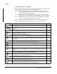
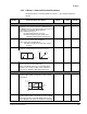
A13 Analog Input Minimum
Sets the starting point (offset) for the analog input
range. Refer to diagram in A11 [
ANALOG FREQUENCY
MINIMUM]
0 to 99 1% 0
A14 Analog Input Maximum
The ending point (offset) for the analog input range.
Refer to diagram in A11 [
ANALOG FREQUENCY MINIMUM]
0 to 100 1% 100
A15 Analog Start Select
Sets the output frequency when frequency reference is
below value set in A13 [
ANALOG INPUT MINIMUM].
Settings: 00 = A11 [
ANALOG FREQUENCY MINIMUM]
01 = 0 Hz
00 to 01 Numeric
Value
01
A16 Analog Filter Select
Sets the level of the Analog input smoothing filter where:
1 = low (Bandwidth = 200 Hz)
8 = high (Bandwidth = 25 Hz).
1 to 8 Numeric
Value
8
Preset Frequencies
*A20 Internal Frequency
When A01 [
FREQUENCY COMMAND SELECT] is set to 02,
this parameter will provide the drives frequency
command. This parameter will change the frequency
command only after the new frequency is entered into
memory.
This value can also be changed via F01 [
FREQUENCY
COMMAND] if no preset frequency inputs are active.
This parameter can be changed while motor is running.
0.0 to 360.0 0.1 Hz 60.0
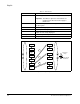
A12
A13
0V
4mA
A14
10V
20mA
% Input
Scale
Frequency
A11
A15=01
A15=00