
Instruction Manual


Parameters and Programming
3-7
English
3.2 Parameter Descriptions
The sections that follow provide descriptions of all drive parameters, separated by
group.
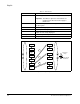
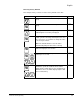
3.2.1 D Group - Display and Diagnostic Parameters (Read Only)
This group of parameters consists of commonly viewed drive operation conditions
such as output frequency. All parameters in this group are Read Only.
Parameter
Number Parameter Name / Description
Min./Max.
Range Units
d01 Output Frequency
Displays the output frequency to the motor.
0.0 to 360.0 N/A
d02 Output Current
Displays the output current to the motor.
0.00 to 999.9 0.01 A
d03 Direction
Displays the present direction of rotation.
F=Forward
r=Reverse
o=Stop
N/A
d04 PID Process Display
Displays the scaled PID Process variable (feedback). Available only
when the PID control is active. The scale factor is set using A75
[
PROCESS REFERENCE SCALE FACTOR].
0.00 to 100.0 0.01%
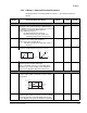
d05 Digital Input Status
Displays the status of the 5 digital inputs regardless of how each input
is programmed in C11 [
DIGITAL INPUT 1 LOGIC] through C33 [ALARM
RELAY AL1 LOGIC].
5 4 3 2 1
N/A N/A
d06 Output Status
Displays the status of the digital outputs and the fault indication
relays.
AL 12 11
N/A N/A
d07 Process Display
Displays d01 [
OUTPUT FREQUENCY] scaled by the variable set in b86
[
PROCESS DISPLAY SCALE FACTOR].
Note: If there are more than 4 digits, the LSB will be dropped.
0.00 to 9990 0.01
d08 Last Fault
Displays the last fault. The output frequency, motor current, and DC
bus voltage at the time of the last fault can be viewed by pressing
PROGram. If there has not been a fault or the register has been
cleared, then --- will be displayed.
N/A N/A
High
Open
High
Open