
Instruction Manual


2-14
SP120 AC Drive Installation and Operation
English
16 {AT} 4-20mA Select Activates input terminal OI for use as a 4-20 mA input. If no input
terminal is programmed for this setting, the factory default input is O
(0-10V) and the output frequency will correspond to the value of the
inputs to the O and/or OI control inputs.
Note: Parameter A01 [
FREQUENCY COMMAND SELECT] determines from
what source the output frequency is commanded.
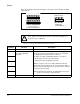
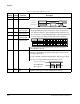
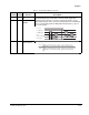
18 {RS} Reset Used to clear a fault condition. If a 18 {RS} command is given during
operation, the output IGBTs are switched off and the motor will coast.
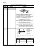
19 {PTC} PTC Input This input can only be programmed to digital input terminal 5 and
the PTC should be referenced to terminal L.
If the PTC resistance exceeds 3k Ohms, the output voltage to the motor
will be switched off and an E35 fault code will be issued.
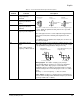
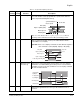
20 {STA} 3-wire run 3-wire (Momentary) control inputs. Both settings 20 {STA} and 21 {STP}
must be programmed as digital inputs for 3-wire control to function. If 20
{STA} is programmed into any digital input then 2-wire (maintained)
control will not function.
Note: 3-wire stop command (21 {STP}) cannot be used to clear a fault.
21 {STP} 3-wire stop
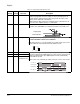
22 {F/R} 3-wire
Forward/Reverse
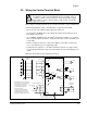
Table 2.5 – Programmable Digital Input Functions
Numeric
Setting
Alpha
Setting Function Description
18 {RS} (NO)
Fault indication
L
5
20{STA} (NO)
21{STP} (NC)
22 {F/R (NO)
Motor Speed